The Right Machine and Process for Mirror-Finish Carbide, Ceramic
One presentation at United Grinding’s recent “Universe” event covered not only a machine of particular interest to toolmakers dealing with such materials, but also general information on what affects surface finish.

Attendees gather around Studer’s S41 OD grinder, which offers various options and wheelhead configurations to suit a wide variety of applications.
Quality surface finish is a top priority for tool and die manufacturers, and machines like those showcased at United Grinding’s recent “Universe” event are among the best ways to achieve it. Hosted in Miamisburg, Ohio September 16-17, the event exposed more than 400 attendees to a wide range of cylindrical, centerless, radius, surface and other grinding technology from the company’s Studer, Blohm, Ewag and Walter brands. One presentation I found particularly intriguing detailed not just a machine of particular interest to toolmakers dealing with extremely hard materials, but also more general information on the factors affecting surface quality.
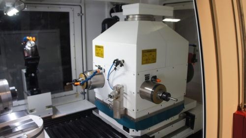
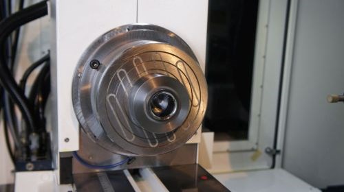
The machine, Studer’s CT930/960 internal cylindrical grinder, has attracted interest from toolmakers dealing with ceramics and carbides that are difficult to machine but as much as 100 times more wear-resistant than most steels, says presenter Andrew Osborn, product engineer. Beyond the capability to handle parts like the carbide draw die shown below, the machine is designed for the flexibilty to handle various internal, external and form grinding tasks in a single clamping. Features include three HF spindles in a linear arrangement (CT930) or four high-frequency (HF) spindles on a rotating turret (CT960); a fully automatic B axis with direct drive and swiveling range of +61 to -91 degrees; a C-axis with digital angle encoders for form and thread grinding; optional swivel-unit A axes; and integrated simulation and measuring cycles. (For specifications and additional information, visit the company’s website.)

Studer’s CT960 features multiple spindles on a rotating turret and an integrated measuring probe.
Yet, achieving better than 1 Ra off the machine (a feat demonstrated with the draw-die application) requires not just the right grinder, but the expertise to know how to use it. Here three bits of surface finish wisdom from Osborn’s wide-ranging presentation:
Oscillate slow, rotate fast. ID grinding applications involve a complex interplay between the rotation of the workpiece and the oscillation of the grinding wheel. The faster the wheel oscillates, the rougher the finish (but the greater the amount of material removal). With workpiece rotation, this equation is reversed—a slower-rotating workpiece produces a rougher finish, while faster rotation produces a smoother finish. The precise values vary from application, but the best finish is typically achieved from a slowly-oscillating wheel and a quickly-rotating workpiece, Osborn says.

The CT960 on display at the “Grinding Universe” event achieved a 1-Ra surface finish on the ID of this carbide draw die.
Choose the right process. Whether grinding internal or external radii, manufacturers typically turn to one of three strategies: plunge grinding, in which a wheel dressed with the reverse-shape of the profile is driven into the workpiece; contour grinding, in which one section of the wheel carves out the desired profile; and pendulum grinding, in which the wheel swivels back and forth horizontally (a strategy that requires a machine with a swiveling B-axis workhead). Of the three, pendulum grinding tends to provide the fastest cycles, the best surface finish, the least wheel wear, the lowest wheel cost, and the easiest dressing, Osborn says. However, it’s not always possible for all open-form radius grinds, and it simply doesn’t work for closed-form applications. In the latter case, Osborn says plunge grinding is the best option if cycle time is the chief concern, while contour grinding is better suited for quality surface finishes, easier dressing and lower wheel costs.
Mind your measurements. Although charts exist to convert between Rz and Ra measurements, Osborn says its important to understand that these are just general guidelines. When it comes to exacting measurements, one value cannot be directly converted to the other. The difference? Rz (roughness depth) measures the average distance between the highest peak and the lowest valley, while Ra (roughness average) is the arithmetic mean of the absolute value of the highest and lowest peaks.
More information from United Grinding is available on the company’s website.
Read Next
Reasons to Use Fiber Lasers for Mold Cleaning
Fiber lasers offer a simplicity, speed, control and portability, minimizing mold cleaning risks.
Read MoreHow to Use Strategic Planning Tools, Data to Manage the Human Side of Business
Q&A with Marion Wells, MMT EAB member and founder of Human Asset Management.
Read MoreHow to Use Continuing Education to Remain Competitive in Moldmaking
Continued training helps moldmakers make tooling decisions and properly use the latest cutting tool to efficiently machine high-quality molds.
Read More


