Software Environment Provides “CAD for CAM” Functionalities for Programmers
Two CAD function formats have been integrated into the hyperMILL environment to lessen the impact for users working in CAD or CAM.
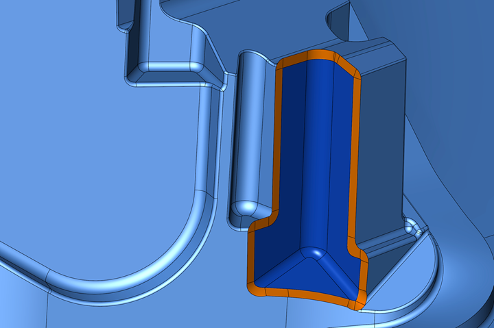
Automatic surface extension within the CAM strategy enables toolpath improvements to ease entry/exit and avoid rollover at the sharp edge. Photo Credit: Open Mind Technologies
Open Mind Technologies offers a working environment in hyperMILL software that focuses on “CAD for CAM,” addressing the requirements of CAM programmers who are not traditional CAD users. HyperMILL CAD for CAM provides two formats for CAD functions to enable selections and interaction.
The first approach is a traditional CAD front-end. Here, the user has a working environment to import CAD data, create and edit curves, surfaces and solids, as well as utilities for move, copy and pattern commands. Then there are additional functions targeted for CAM users including radius and draft analysis, curvature and zebra maps, co-axial and co-planar selections, and tags to easily arrange features such as all fillets of a certain size. Additionally, there are some advanced functions to refit a surface or mesh to simplify the model or improve the machining process, and deformation capabilities to account for expected machining deflections or spring back during the post-machining stamping process. Open Mind says this breadth of functionality provides users with easy and powerful CAD capabilities.
Secondly, Open Mind has merged its CAD and CAM development teams to further integrate CAD requirements directly in hyperMILL CAM strategies. The result of these developments is impactful to the user, saving keystrokes and lessening the impact of working in the CAD or CAM environment. A few examples include the following:
- Machining boundaries can be selected by hovering a mouse near an edge, without creating the boundary curve as a CAD entity.
- Surfaces can be automatically extended over external edges. This process checks and avoids overlaps in the extended region. The benefit is the ability to generate tool paths that produce a sharp edge without roll-over, and without CAD construction.
- Drive curves for swarf cutting can be generated automatically over multiple surface patches including corner blends.
The benefit of these CAD for CAM functions offered in hyperMILL reduce clicks and programming time, freeing up programmers to focus on manufacturing tasks.
Related Content
-
Tolerancing in Mold Design, Part 1: Understanding the Issues of Conventional Bilateral Tolerancing
Mold designers must understand the location, orientation and form limitations of conventional tolerancing before changing to another dimensioning system.
-
What Is Scientific Maintenance? Part 1
Part one of this three-part series explains how to create a scientific maintenance plan based on a toolroom’s current data collection and usage.
-
It Starts With the Part: A Plastic Part Checklist Ensures Good Mold Design
All successful mold build projects start with examining the part to be molded to ensure it is moldable and will meet the customers' production objectives.


