Why You Need 3-D CAD Now
Today's moldmaking 3-D CAD software allows for faster speed-to-market, error reduction, cost savings, better designs and business success.
In five years, companies that are still exclusively designing molds and other products with 2-D mechanical design software will be out of business-or at least in a very different business. 2-D design will be virtually obsolete, eclipsed by the speed, efficiency, accuracy and short learning curve of 3-D mechanical design software. This evolution is as inevitable as word-processing software displacing the typewriter.
2-D Versus 3-D
3-D design differs from 2-D design in a pivotal way: in 2-D, drawings are the master documents that define how each part in a tool assembly should be made and illustrate how the product comes together. Drawings may be made on a drafting board or, more commonly, with 2-D CAD systems. Today, models are the master with 3-D CAD.
Injection mold builders have employed a combination of 2-D and older-generation 3-D CAD/CAM systems since the 1980s, but they haven't reached their potential speed, efficiency and productivity. Models used for milling mold core and cavity surfaces have typically consisted of 3-D wireframe and surface models. However, today's new CAD systems, which employ solid models, generally perform better for complex milling because they eliminate confusing lines that should be hidden. This makes it easier to visualize tool positions or ensure that only the right material is being removed.
Meanwhile, many moldmakers who use 3-D CAD/CAM for milling still employ 2-D drawings for designing the complete mold-base assembly. Mold assemblies contain hundreds of parts, and computer workstations have traditionally lacked the power to model all of these effectively in three dimensions. Yet, when mold assemblies are represented in 2-D, mistakes in drawings or in their interpretation are common and costly. Companies must rework, or even scrap, incorrectly made molds or tools.
The Next Generation
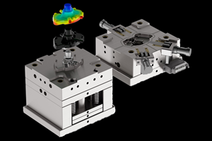
New, efficient desktop 3-D design software eliminates these problems by creating an unambiguous solid model of a mold assembly. Working with topologically complete and accurate models, engineers and designers can ensure that parts fit properly and function as intended before tools are made. 3-D models enable designers to better visualize where to put cooling lines to maximize heat removal and minimize cycle times.
Using 3-D solid models, moldmakers also can take advantage of rapid prototypes made by additive fabrication techniques to verify that part models are correct before designing molds. These 3-D mockups also are valuable aids to mold designers, helping them to see how to position parts in the mold and where cams or sliders must be used to mold parts with undercuts. Using processes like selective laser sintering, mold designers can fabricate mold inserts with conformal cooling channels to further optimize cycle times. Designers also can use 3-D digital mockups to verify that designs not only fit together but that they work properly.
Working in 3-D doesn't require ignoring drawings altogether. Moldmakers and designers can produce drawings more quickly from 3-D models than by manual or 2-D computer-aided drafting techniques. Errors in projecting views that are common in 2-D drafting simply can't occur when computers project unambiguous drawing views from 3-D product models. Moreover, designers can change drawings more quickly with 3-D CAD because a single change in the 3-D master model updates all drawing views with perfect accuracy.
Another benefit of 3-D CAD is the increasing interoperability with complementary software, including analysis programs. For example, 3-D CAD interoperates with mold filling and cooling analysis programs to ensure that parts don't warp or show shrink marks, and that companies can meet production cycle times. Kinematic analyses can ensure that mechanisms such as cams and sliders don't interfere with other parts of the tool.
When it's time to make the tool, 3-D computer models, not drawings, are the geometry master. The toolmaking plant puts these masters to many uses. Numerically controlled mills can cut core and cavity surfaces from the models. Tool surfaces and first articles can be inspected using optical scanners or coordinate-measuring machines and compared to the 3-D CAD master. The master can generate bills of material for cost estimating, purchasing and manufacturing resource planning.
Economic Benefits of 3-D Design
3-D CAD modeling has become the accepted method for automotive and aerospace design because it offers a wide range of compelling economic benefits. A wide range of companies making consumer, office and medical products also use 3-D CAD.
By directly employing 3-D models into the toolmaking process, tooling shops can save labor and reduce delivery times. Shops can identify and correct mistakes in tool designs before making production tools. The cost savings from being able to spot interferences, inaccurate dimensions, components that are inaccessible for maintenance purposes and arrangements that cannot be assembled efficiently, outweigh the cost of 3-D design software.
The ability to employ 3-D models for physical analysis, NC programming and inspection dramatically reduces the time and cost needed to perform these tasks. As a result, manufacturing becomes more economical even as it improves product reliability, fit and safety. 3-D master models also reduce drawing costs by automating view creation and eliminating the need to show as many cross-sectional views as would be needed with a purely 2-D approach.
Lastly, producing tools directly from 3-D models almost always results in shorter leadtimes. Shorter production schedules-especially when making tools for style-conscious markets-can generate significantly more revenue because faster deliveries command higher prices.
Fully assessing the considerations listed in the Selection Criteria for a 3-D Design System sidebar at the end of the article, and adopting the 3-D CAD system that best meets your needs will ensure that your organization reaps all of the potential benefits of moldmaking 3-D design software, including speed-to-market, error reduction, cost savings, better designs and, ultimately, business success.
| Selection Criteria for a 3-D Design System |
The characteristics to evaluate when choosing a 3-D CAD system for 3-D design differ from those that are important to buyers of 2-D CAD systems. For 3-D design, managers should examine:
|
Related Content
Tips for Tackling Mold Design, Machining, Cutting Tool and Wear Challenges
Tips for tasks ranging from reducing risk in part design and taking advantage of five-axis machining to refining cutting tool performance and reducing wear with guiding and centering systems.
Read MoreTolerancing in Mold Design, Part 1: Understanding the Issues of Conventional Bilateral Tolerancing
Mold designers must understand the location, orientation and form limitations of conventional tolerancing before changing to another dimensioning system.
Read MoreWhat is Scientific Maintenance? Part 2
Part two of this three-part series explains specific data that toolrooms must collect, analyze and use to truly advance to a scientific maintenance culture where you can measure real data and drive decisions.
Read MoreWhat Is Scientific Maintenance? Part 1
Part one of this three-part series explains how to create a scientific maintenance plan based on a toolroom’s current data collection and usage.
Read MoreRead Next
Choosing CAD Software For 3D Mold Design
The world of CAD offers many alternatives to shops that want to use the latest 3-D technology for their mold design. This article looks at the benefits of the various approaches and offers some tips on choosing the most appropriate one.
Read MoreAre You a Moldmaker Considering 3D Printing? Consider the 3D Printing Workshop at NPE2024
Presentations will cover 3D printing for mold tooling, material innovation, product development, bridge production and full-scale, high-volume additive manufacturing.
Read MoreHow to Use Continuing Education to Remain Competitive in Moldmaking
Continued training helps moldmakers make tooling decisions and properly use the latest cutting tool to efficiently machine high-quality molds.
Read More


