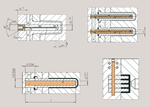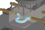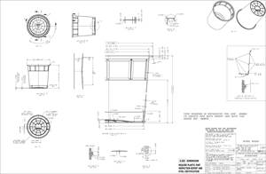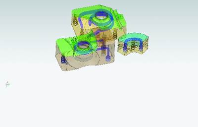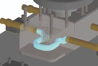
This image shows a typical eight-cavity gear mold from the 1980s. The B-side cooling was looped in the base surrounding the cavity insert. Due to the thin walls and small volume of molten plastic being cooled, this cooling method was sufficient. The cavity surface temperatures were able to recover quickly after each injection cycle. Source (All images) | DJC Plastic Consulting LLC
Mold builders and molders know that cooling is critical to the molding process, as uneven or insufficient cooling can impact dimensions and surface finish and lead to internal voids, sink marks, warping and molded-in stresses, but it often remains an afterthought.
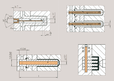
Common mold cooling challenges include difficulty cooling the core because ejector pins are in the way or long, thin mold features that limit cooling channel access. Cooling lines usually can’t be drilled from the side above the parting line, so they are not as near to the top surface as desired. As a result, core blocks do not receive enough cooling. Baffles or bubblers may be needed to bring proper cooling near the top surface, and although conformal cooling can overcome some of these limitations, it is not yet a widely used technology.
In addition to these challenges, many molds are designed by first placing the ejector pins, screws, etc., into the mold design, with the areas for cooling lines being considered last. It is better to first design the optimal cooling scheme and then add ejector pins, screws, inserts, etc. Sometimes, you may need to compromise and relocate the cooling lines to accommodate these components, but it's crucial to maintain as close to optimal cooling as possible.
The question at hand is: How much cooling is required? The answer is that enough cooling is needed to produce an acceptable part in the shortest amount of time at an acceptable tool cost. This is a vague statement and can only be defined by those most familiar with the project. For a prototype or low-volume mold, tooling cost may be the driving factor and cycle time may be less important. However, tooling cost may be secondary for high-volume commodity parts, where part cost is paramount, so optimum cooling and minimal cycle time are critical.

Providing cooling water channels around each individual cavity typically offers better cooling performance than only cooling the base, especially when molding parts with higher mass. However, connecting all eight cavities in series on a single cooling line could lead to a significant temperature increase in the cooling water from the first cavity to the last, potentially reducing cooling efficiency.
Mold Cooling in Action
Molten plastic only reacts to the steel it contacts on the mold surface. The rate of plastic cooling is only affected by the immediate surface skin of the mold. The rest of the heating or cooling of the mold only indirectly affects the plastic, as it is used to achieve the optimal mold surface temperature. Heat flows through steel and other metals at a rate based on the surface areas of the cooling lines and cavity surface, the distance between them, the temperature difference between the hot plastic and cooling medium and the thermal conductivity of the mold metal.
Much has been written about achieving a high Reynolds number to induce turbulent flow in the cooling lines. While this is important, other considerations may significantly impact the cooling rate. A high Reynolds number may not provide sufficient cooling if the distance between the cooling line and the cavity surface is too large, if there is an air gap between the steel with the cooling line and the cavity steel (for example, if only the mold plates are being cooled and not the cavities) or if corrosion in the cooling line creates a thermal barrier.

Designing cooling channels to surround each cavity individually and looping only two cavities ensures more uniform temperatures across all cavities. This approach becomes even more critical when molding parts with greater plastic mass or when dealing with more constricted cooling lines.
Cooling Cases in Point
Looping cooling lines or having cooling channels that are too long can lead to the cooling liquid heating up too much from the inlet to the outlet. A general rule of thumb is to have a 5oF (3oC) difference between the inlet and outlet water temperature. I once saw a multi-cavity mold at a custom molder that had a single inlet and outlet on each half. In this case, the inlet water was 60oF (16oC), but the outlet water was almost boiling. The molder thought this was great because ‘the water is pulling out a lot of heat’. However, although it was pulling out a lot of heat, the cycle time was limited by the hottest cavities. This led to differences in mold filling, shrinkage and internal stresses from the coolest to the warmest cavities.
Another customer insisted that each mold feature should have its own cooling inlet and outlet, even for a mold that fits in a 200-ton press. This resulted in a large number of inlets and outlets, requiring six-foot water manifolds on each half of the mold. (I am not exaggerating — two three-foot manifolds in series on each half.) It seemed like overkill for the size of the mold. However, when the mold was put into operation, the temperature across its surface varied by only one degree Fahrenheit. This made me question whether it was necessary, but perhaps the customer's experience with similar parts led them to prioritize optimum cycle time and part quality over the added tooling and setup cost.
Optimum cooling varies from part to part and from mold to mold, but one thing remains constant: cooling must be carefully considered during the design of every mold.
Related Content
Leading Mold Manufacturers Share Best Practices for Improving Efficiency
Precise Tooling Solutions, X-Cell Tool and Mold, M&M Tool and Mold, Ameritech Die & Mold, and Cavalier Tool & Manufacturing, sit down for a fast-paced Q&A focused on strategies for improving efficiencies across their operations.
Read MoreHow to Select a Mold Temperature Controller
White paper shares how cooling channel analysis, which collects maximum pressure drop, total flow rate and heat dissipation, eases the performance evaluation of mold temperature controllers.
Read MoreIt Starts With the Part: A Plastic Part Checklist Ensures Good Mold Design
All successful mold build projects start with examining the part to be molded to ensure it is moldable and will meet the customers' production objectives.
Read MoreFour Micro Tooling Considerations
Issues involving gating, ejection, mold splits and direction of pull are of special concern when it comes to micro tooling.
Read MoreRead Next
Fundamentals of Designing the Optimal Cooling System
The right mold components can help improve mold cooling and thereby produce higher-quality parts.
Read MoreConformal Cooling: Another Tool to Build a Better Mold
Moldmakers are just starting to scratch the surface of what can be done with conformal cooling, which involves an additive approach.
Read MoreHow to Supply Cooling to Additive Tooling
Additive tooling provides limitless options for cooling a mold’s difficult-to-cool areas.
Read More

