Why Simulation Matters in Mold Design
If you design molds for a living, chances are there’s simulation software out there that can help you do your job more effectively. But what type of software should you be looking for? The answer is software that enables digital prototyping.
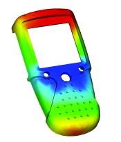
Digital prototyping gives designers and engineers the ability to virtually explore a complete product before it is built—so they can design, visualize and simulate products from the conceptual design phase through the manufacturing process. By using a digital prototype, users access real-world performance of a design with less reliance on costly physical prototypes.
While simulation has been a part of moldmaking processes for quite some time, it has historically been used to drive troubleshooting and validation efforts, rather than design. The problem with limiting simulation to these areas is that it focuses on problem fixing and problem-avoidance, rather than on trying to create truly optimized designs. Simulation software should predict and optimize how components will perform throughout each phase of the design and manufacture process.
Digital prototyping aims to bring simulation into the process much earlier, so designs can be optimized using analysis results. Changes are much cheaper to make digitally on a computer than on a piece of steel that’s already been cut. Nobody knows this more than moldmakers: mold costs can easily run from as low as $10,000 to more than $100,000, depending on the complexity of the mold. The more complex the mold, the higher the cost—and the more important it is to use simulation.
By implementing simulation earlier in the development stages, mold designs can be analyzed and improved iteratively so potential problems are solved preemptively and products are optimized prior to starting production. This method has proven to be extremely effective because quality is now designed into the product and less testing is required in the later stages, which improves the overall efficiency of new product development.
For moldmakers and mold designers who are “down in the trenches”, the right digital prototyping package translates into a host of benefits, including the ability to verify part design manufacturability and quality; the ability to lay out and optimize the gate and runner systems for single-cavity, multi-cavity and family molds; and, the ability to predict processing requirements and quote mold jobs.
Example 1: Runner Balancing
For an example of virtual simulation in action, it is useful to examine a classic moldmaking challenge: runner balancing.
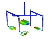
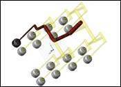
Runner balancing is a major factor in mold design optimization and is absolutely necessary in the case of family molds, where the cavities are of different sizes and shapes. An unbalanced feed system will produce parts of variable quality. The goal of balancing the feed system is to achieve similar filling times and pressures for all mold cavities while minimizing the amount of material used in the feed system.
With the runner balance analysis provided by digital prototyping software, mold designers can set up and balance tool configurations of all types, very quickly and easily. Users have the option of selecting specific runner segments for balancing or they can set maximum and minimum limits on each segment so that they have an added measure of control.
Additionally, users can input their standard cutting tool sizes into the software, and the runner balance analysis will automatically balance the runner system so that it can be milled in these specified sizes. Users can choose to review the runner-balancing results segment by segment or apply the results to all segments automatically. The net result? Less costly rework later down the road.
Example 2: Core Shift
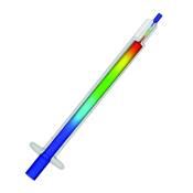
Digital prototyping also can be beneficial with simulating core shift in plastics injection molded parts and predicting injection molding machine clamp over-tonnage.
Core shift causes wall thickness variation, which results in both structural and cosmetic defects. For high precision parts, the core deflection can lead to rejects or a premature service life failure.
Designers can use a simulation software package’s core shift analysis results to correct the phenomenon, by adjusting process settings or modifying the mold design as necessary, reducing the costs of design-to-manufacturing process of a part and decreasing the time-to-market.
Choosing a Simulation Software Package
To enable effective simulation in the design process, companies should keep a few key elements top of mind:
- Simulation software should be easily accessible by any member of a design-to-manufacturing team, and the user interface and number of analysis options should be configurable based on job function, knowledge, skill and experience.
- The software should integrate easily with existing CAD applications, and should export to a number of industry standard formats, including Microsoft Word and PowerPoint.
- Lastly, the software must come with a strategic implementation plan that covers everything from licensing and training, to technical support and material testing to ensure simulation is incorporated into the best practices of the organization.
Conclusion
Simulation is arguably more important for mold design than any other phase of the manufacturing process. By following the recommendations outlined in this article, moldmakers can make digital prototyping a reality—and a resounding success—within their organizations.
Related Content
OEE Monitoring System Addresses Root Cause of Machine Downtime
Unique sensor and patent-pending algorithm of the Amper machine analytics system measures current draw to quickly and inexpensively inform manufacturers which machines are down and why.
Read MoreFour Micro Tooling Considerations
Issues involving gating, ejection, mold splits and direction of pull are of special concern when it comes to micro tooling.
Read MoreLeading Mold Manufacturers Share Best Practices for Improving Efficiency
Precise Tooling Solutions, X-Cell Tool and Mold, M&M Tool and Mold, Ameritech Die & Mold, and Cavalier Tool & Manufacturing, sit down for a fast-paced Q&A focused on strategies for improving efficiencies across their operations.
Read MoreTolerancing in Mold Design, Part 1: Understanding the Issues of Conventional Bilateral Tolerancing
Mold designers must understand the location, orientation and form limitations of conventional tolerancing before changing to another dimensioning system.
Read MoreRead Next
Staying Competitive Using Mold Flow Analysis
The pressure on the supply chain is unrelenting for all things faster, better and cheaper. For moldmakers, getting molds built right the first time is critical to meeting these increasing demands. But how?
Read MoreValidation of Design Guidelines
Flow simulation software integrated with powerful 3-D CAD functionality can be effectively and efficiently applied to validate guidelines for cooling time and runner sizing.
Read MoreDSSP: The Catalyst for a New Revolution
One CAD short- coming—a frequent disconnect between the final manufactured product and the idealized CAD model—is being addressed with digital shape sampling and processing.
Read More

