Unique Five-Axis CAM Programming Helps Moldmaker Meet Strict Specs
When it comes to hard milling and tough surface finish requirements, X-Cell Tool finds one CAM software’s approach answers the call for perfection.
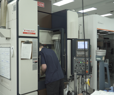
Moldmakers looking to drive continuous improvement using advanced, five-axis CNC machining centers often must contend with the learning curve that comes with the switch from tried and true three-axis machining approaches. Even when machine operators feel they have mastered the five-axis capabilities, there are additional adjustments based on operator knowledge and customer requirements. One of these is having the right software to coax the five-axis technology to produce at the optimum level. X-Cell Tool and Mold (Fairview, Pennsylvania) recently underwent this learning experience with its Yasda YMC-430 RT 10 five-axis Micro Centers.
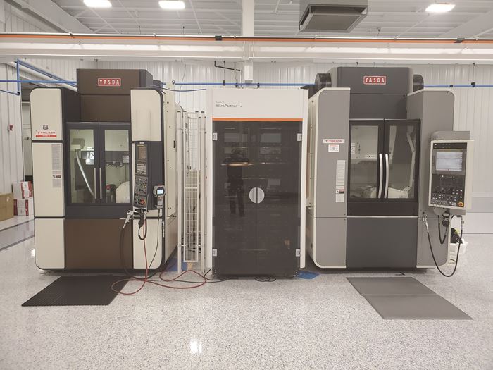
X-Cell is MoldMaking Technology magazine’s 2019 Leadtime Leader Award-Winning shop and has a continuous improvement mentality entrenched in its culture. The company maintains a lead time of between 14 and 16 weeks for complex 32- and 64-cavity molds and was looking to invest in new technology to grow its hard-milling capabilities and optimize its finish machining operations. They invested in the first of two YMC-430 RTs in 2018 (the other delivered in 2019 was the YMC-650 Micro Center). It wasn’t long before X-Cell realized that its current CAM software was not suitable to the Yasda’s speed and agility.
“The Yasda is a very high end, five-axis machine that is guaranteed to be able to hold 0.0001-inch tolerance throughout its window and produce finishes that need almost no polishing,” Jim Cummings, general manager, says. “The software we were using for making very complex electrodes and for hard milling could not get the Yasda where it needed to be in terms of tolerances and surface finish. We needed to find a software that could give us more accurate tool paths. I asked our Yasda representative what software they recommended, and they said CAM-TOOL.”
Surface-Based Tool Paths Make Finishes “Incredible”
Cummings says that he took Yasda’s recommendation and purchased the software on a 30-day trial basis to be sure it was going to do what he needed it to do. “I wanted to see the software in action, programming our work instead of going to CGS, so I picked on-site training at our facility,” he says. Ryan Weekes, B.B.A., president of CGS North America (Oldcastle, Ontario, Canada), and his team spent two days at X-Cell training the lead programmer and demonstrating CAM-Tool features; then they let X-Cell run with it for a week or so, came back to fine tune things and answer questions. Cummings says it didn’t take long to validate the claims.
CAM-Tool was developed for hard milling.
According to Cummings, prior to using CAM-Tool, X-Cell used the old software to program complex, hard-milling jobs (for machining materials ranging from 50RC to 65RC) or an electrode using the former software, but the results were less than acceptable. For example, X-Cell tried to manufacture some very involved electrodes for a customer, and they were rejected for little mismatches between tools and very small tool marks. “When the machining was completed, you could see and feel the lines from where the machine cut,” he says. “Those lines measured about 0.0001 to 0.0002 inch.” The problem, he says, is that when making an electrode, if those lines are present, they will burn into the steel and are difficult to polish out. “The stone is rubbing low spots and high spots, and the lines never seem to want to disappear,” he says. “When I took the same approach using CAM-Tool – same entry, same feed rates, everything, all those little flaws were gone. The surface finish was incredible.”
Asked what feature in CAM-Tool makes it so much more superior, Cummings says it is in how it calculates the tool path using the surface model not a mesh.
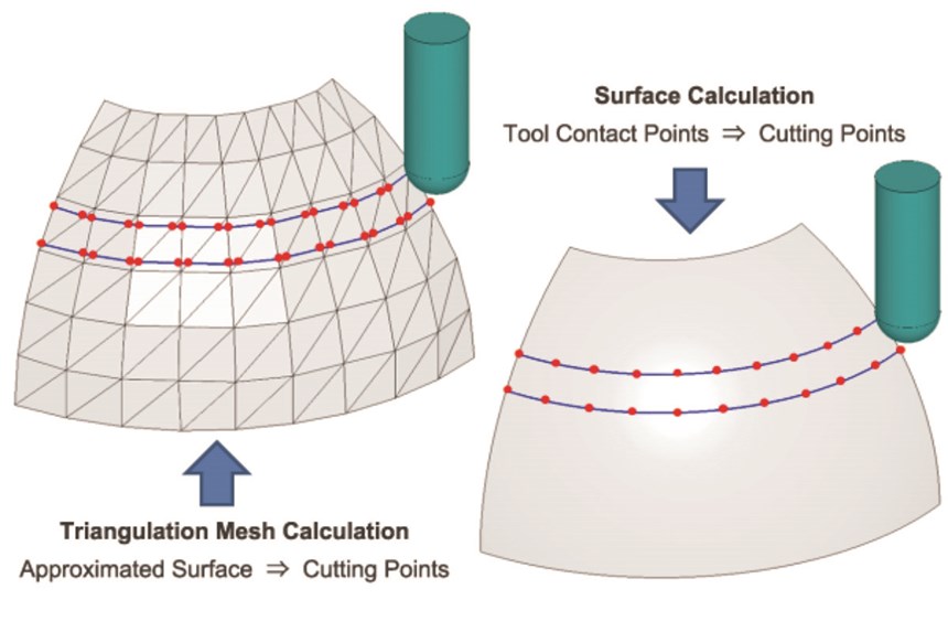
“Most people don’t realize that CAD/CAM software can actually cause accuracy issues,” CGS’s Weekes says. “They think that once they create that NC code and get it to the machine, that all NC code is created equal. It’s not.” He explains that most CAM software uses triangulation mesh (like a net made of little connected triangles) over a solid model to calculate tool paths, so the resulting tool paths are often approximate and therefore not as accurate. CAM-Tool uses surface-based calculations, creating a high number of NC data points that are directly offset off the workpiece’s surface, so you're getting a true representation of what your model is. “Many of the newer machines from Yasda, Roeders and Makino have controls that prefer to have as many points as possible because it helps the machines run more accurately and efficiently. CAM-Tool puts out more points than any other software that I have seen, so when your NC code goes to the machine, it is getting more accurate code to follow.”
CAM-Tool is the software for writing programs that match the capabilities of the newer cutters and machines.
Cummings adds, “CAM-Tool was developed for hard milling and we use it only for hard milling and machining electrodes. I would say our surface finishes got 25 percent better.”
More than that, Cummings says his polishers tell him that workpieces are polishing up to two times faster than usual. “We just worked on a mold for a large medical part and the mold had 64 identical cavity inserts in it,” he says. “Each insert had to have an optical diamond finish. Our polishers said they were amazed at how quickly they could achieve that level of finish.” He estimates that when X-Cell’s polishing department is working on parts machined using CAM-Tool, they are cutting about 25 to 30% off the time required to attain desired finishes.
“I have the best cutters and high-RPM machines, and I can program in the other software and still not get to that finite finish,” Cummings says. “CAM-Tool is the software for writing programs that match the capabilities of the newer cutters and machines. It’s the complete package that gets us to those high-end finishes.”
Tighter Tolerances Meet Tough Requirements
In addition to improving surface finish, CAM-Tool has helped X-Cell achieve much tighter tolerances than it ever had before. Cummings says the standard tolerance on most of the company’s work is 0.0002 inch, so tool paths need to be perfect, and right the first time. But before CAM-Tool was implemented, X-Cell put its old software to the test for a very important project and he says it was challenging, to say the least.
They checked it 100 different ways from Sunday and could not find a flaw.
“We have a customer that requires extremely tight tolerances on an electrode we were making for a government project I can’t go into detail on,” Cummings says. “The part had to be absolutely perfect. We machined it and the customer would check it and come back to us saying it was a tenth off here and a tenth off there. We would think, okay, but it was cut right to the model, but being an ITAR (International Traffic in Arms regulation) situation, it has to go through every kind of scrutiny.” After further attempts were rejected, X-Cell purchased CAM-Tool and used it to machine the exact same electrode. “They checked it 100 different ways from Sunday and could not find a flaw.”
Weekes says that CAM-TOOL calculates the location of component points in the tool path using CGS’s proprietary algorithm, corresponding to the curvature of the shape of the model. “That algorithm works in the background and takes the actual surfaces and projects points from it, offsetting the surfaces that you're trying to cut and creating more accurate tool paths.” He says most other software creates an STL (mesh) file in the background and uses that to import triangulated geometries into the CAM system to calculate the tool path, which, as mentioned previously, is not as accurate.
Cummings says X-Cell still uses the other software for programming on other machines, “but when it comes to real high-tolerance 3D geometries, I have to go to the more advanced software that is CAM-Tool. Both have their place, but CAM-Tool improved our tolerances by 0.0001-0.0002 inch.”
Roughing Strategy Keeps Cutter on Path, Saving Time
“Another unique thing about Cam-Tool is that the cutter stays down in the cut longer than it does with our other software, which cuts machining times,” Cummings says. For example, if he programs the other software in the same exact way the cutter tends to lift out of the cut, go to a different location and start again. “CAM-Tool stays in the cut.”
We have probably gained 10 to 15% in tool life.
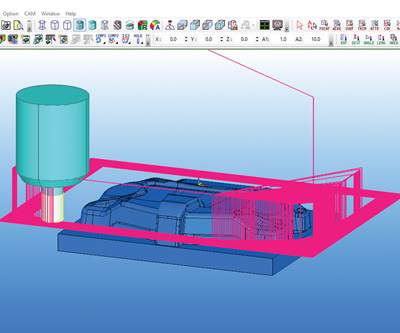
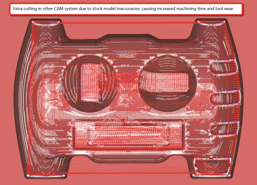
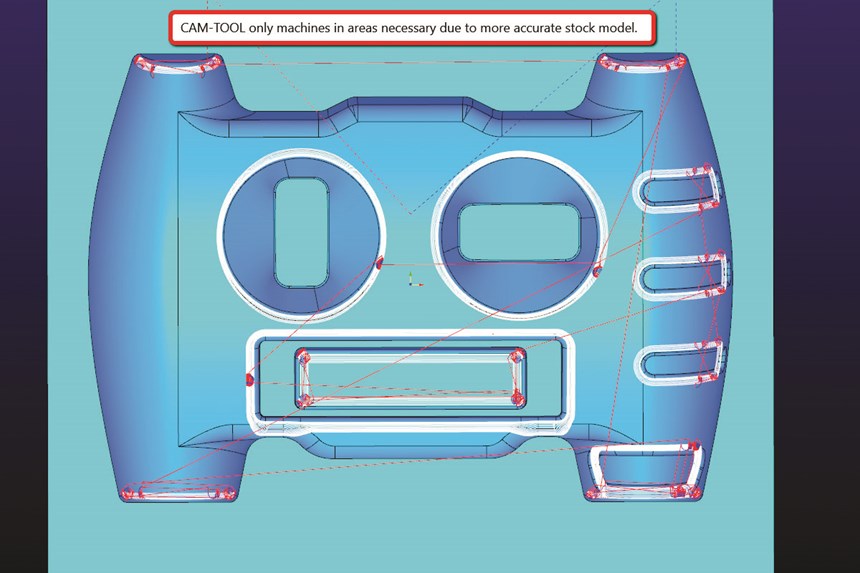
Weekes says Cummings is referring to CAM-Tool’s Z-level roughing strategies using stock model recognition, and how the software sets up the stock model at the beginning of every project and references it continuously throughout the machining cycle. He offers an example. “Say X-Cell is roughing a part using a half-inch cutter. They will cut as much as they can with that cutter and then index to a quarter-inch cutter or something smaller. But they don’t want to use that smaller cutter and recut the entire part, so with our stock model recognition feature, CAM-Tool is able to understand that it only needs to cut in the areas that the half-inch cutter could not get into. CAM-Tool constantly updates the stock model. It understands where the remaining stock is and ensures that the most effective roughing strategy is being used.”
As a result, Cummings says X-Cell is realizing longer cutting tool life on top of more efficient machining times. “Our Yasda operator mentioned to me that he believes he’s going through about 10 percent fewer cutters because of the Z-level roughing function in CAM-Tool. We have probably gained 10 to 15 percent in tool life,” he says. “When you put a $90 cutter in there, 10 percent adds up over the course of a year.”
For More Information
Related Content
Precision Meets Innovation at IMTS 2024
After attending IMTS, it's clear that the integration of advanced technologies is ready to enhance precision, efficiency and automation in mold manufacturing processes. It’s a massive event, so here’s a glimpse of what the MMT team experienced firsthand.
Read MoreThe Trifecta of Competitive Toolmaking
Process, technology and people form the foundations of the business philosophy in place at Eifel Mold & Engineering.
Read MoreHow to Eliminate Chatter
Here are techniques commonly used to combat chatter and guidelines to establish a foundation for optimizing the moldmaking process.
Read MoreRead Next
2019 Leadtime Leader Award Winner: X-Cell Tool and Mold Inc.–The Continuous Drive for Perfection
Continued investment in new technologies and automation has enabled this moldmaker to maintain shorter lead times no matter how large or complex the mold build.
Read MoreStepping Up to the Challenge
This roughing strategy helps maximize metal removal rates and reduce roughing cycle times.
Read MoreAre You a Moldmaker Considering 3D Printing? Consider the 3D Printing Workshop at NPE2024
Presentations will cover 3D printing for mold tooling, material innovation, product development, bridge production and full-scale, high-volume additive manufacturing.
Read More


.jpg;maxWidth=300;quality=90)


