Top 10 Machine Vision Improvement Opportunities
As the global manufacturing market continues to get more competitive, it is important to ensure that automation processes are running at peak efficiency levels. Any process-related malfunction is considered downtime, and directly impacts company profitability. Machine vision is an area that, when set up correctly, can reduce process inefficiencies.
Here are 10 areas for moldmakers to look at when it comes to improving machine vision:
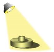
1) Lighting Technique: Backlighting, bright field, grazing, low angle linear array and dark field are various techniques used in machine vision applications. Depending on the part surface finish and contour, the correct lighting will enhance flaws or remove image noise, increasing efficiency and stability.
2) Lighting Color: Each color—UV, blue, green, yellow, red and infrared—renders different frequencies and wavelengths, which determines how the surface of the object and camera will react when light is introduced. The intention is to use the light frequency that will create the greatest contrast and eliminate noise in the image.
3) Filtering: Are you eliminating background or overhead lighting noise and other harsh environment disturbances with lens filters? By simply placing a filter on the camera lens that matches the frequency of lighting illuminating the part, ambient lighting disturbances can be removed.
4) Field of View and Region of Interest: The correct focal length lens will determine the size of the region the system can inspect. A FOV too large will result in less detail and accuracy, whereas a FOV too small may result in the part being out of camera sight. It is important to determine the maximum region of interest and the maximum acceptable error of that region before deciding which focal length lens is appropriate.
5) Location: It is important to have some type of physical fixture that limits the motion of the part of interest. If the part shifts out of the camera view, failure will occur and cause downtime.
6) Calibration: A calibration routine can ensure that the system meets the required quality standards.
7) Features and Fiducials: In order to properly inspect an image, the identification of a unique part feature that is present in every inspection image can be used as a point of reference.
8) Resolution: Determining the resolution of the system is important because it determines how accurate and repeatable the inspection can be. If you have a system in which the resolution is .5mm/pix and you need to measure a part +/- .1mm it may be impossible to achieve.
9) Stability: It is important to ensure that the mounting of the camera system and lights do not move or shift during the process. Also, when setting up the equipment, it’s wise to place the cameras and lights in areas with little or no vibration or in areas with little traffic.
10) Testing: A testing procedure can be built into the system to ensure that the process is efficient. Test parts are referred to as rabbit parts that can be placed into the system to verify proper functionality.
Related Content
-
The In's and Out's of Ballbar Calibration
This machine tool diagnostic device allows the detection of errors noticeable only while machine tools are in motion.
-
Solving Mold Alignment Problems with the Right Alignment Lock
Correct alignment lock selection can reduce maintenance costs and molding downtime, as well as increase part quality over the mold’s entire life.
-
The Benefits of Hand Scraping
Accuracy and flatness are two benefits of hand scraping that help improve machine loop stiffness, workpiece surface finish and component geometry.


