Surface Finish Considerations for Better Molds
Mold material, tolerances, texture, mold release, flow, splay, hand finishing, machining and software impact surface finish decisions.
Surface finish is one of the most important considerations when creating a mold. Key factors include mold material and customer-required tolerances. For example, silicon requires a mirror finish to work properly, as sometimes the finished piece cannot be touched and residue and oil from machinists’ hands cause issues. Aesthetics also can play a huge role in surface finish decisions, as the the mold’s surface finish could dramatically change the final part’s application. Here is a look at a few more surface finish considerations for making better molds.
Texture. Some molds need to be textured. For example, if operators are making a mold of a medical part—like an endoscope, which a surgeon needs to hold with gloves—they will need to develop a uniform texture for gripping. Medical utensils often need to have a highly tactile capability. The grip is part of that, but something as basic as how the tool feels also is important. When surgeons are doing delicate work, they need to be able to hold their tools properly, and the tool should also feel comfortable in their hand.
Mold release. Certain materials will not release with inconsistent or flawed surface finishes. For example, silicone, thermoplastics and metal injection molding commonly require high-quality surface finishes for proper ejection from the mold cavity. Some materials will have this issue intermittently if the mold has a poor surface finish, which can cause more headaches with not only the final parts but also with mold life. For example, silicone and many nylon materials can have sticking issues, even if the surface finish is perfect. In this situation, shops should add surface texture to ensure the best possible chance of manufacturing a high-quality part.
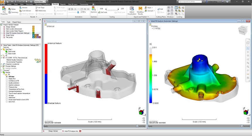
Flow. As the machine injects material into the mold, it must be able to get into every nook and cranny of the cavity. However, different surface finishes can change how the material flows, potentially preventing it from filling, resulting in insufficient filling pressures or material freezing prematurely. Simulation software is available to analyze molds at the early stage before CAM programming has begun. For example, Autodesk’s Design Adviser checks how the part design aligns with manufacturability of the mold by providing input regarding draft angles, undercuts and thickness variations. The Gate Location, Runner Adviser and Runner Balance sequences provide recommendations to optimize the mold performance, such as suggesting the best size, position and some gates to add.
Highly accurate simulation routines can then be used to analyze how the material will flow into the mold. These help to identify problems, such as inadequate filling, weld-lines and cooling efficiency early in the process, giving moldmakers increased confidence that the design is ready for CAM programming. The simulation uses an extensive database of more than 10,000 tested materials to help maintain high levels of accuracy.
Splay. A sub-par surface finish can also cause issues with splay, sometimes called “silver streaks.” Splay appears as silver scratches on the finished part, which is caused by minuscule gas bubbles dragged across the part’s surface as the mold cavity fills.
When a material is heated before being injected into a mold, there is often moisture in that material. This moisture turns to steam as the material is heated, and the result is tiny gas bubbles in the injected material. As the part is cooling in the mold, these gas bubbles migrate to the surface and cause splay. While this issue is a cosmetic problem, it can also weaken the structural integrity of the molded part.
While shops can prevent splay by verifying that material dryers are working correctly so the material dries completely, it can still sometimes present a challenge. To help prevent scenarios where moisture may still be present within the mold cavity, adequate venting can be incorporated into the mold. Vents are designed to allow air and gases within a mold to escape as it is filled, and with the right surface finish, those gas bubbles can be ushered to vents as well, reducing splay. Moldflow Insight from Autodesk offers a vent simulation to analyze the efficiency of planned vents in the mold.
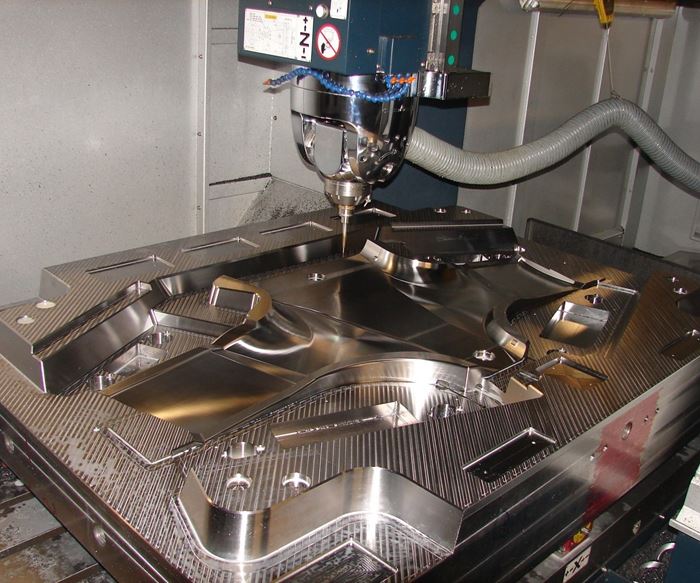
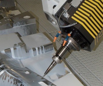
Hand finishing. Most of the time, molds undergo an array of processes to get to their final form. When machining a mold, running times of 40, 80 or even 100 hours is nothing. A traditional machinist will probably be familiar with using a ball end mill to get contoured surfaces, but when making a mold, it is not uncommon to use single-point tools. These can take a long time to machine a part with a tiny stepover and high rpm, but it makes for a much better surface finish.
In a mold shop situation, machinists typically are not thinking about production. They are thinking about customized, quality parts that other facilities will use in production environments. Because of this, time is less of a factor than it is in a traditional machine shop, so getting the best surface finish possible with automation helps keep the rest of the shop moving. A good rule of thumb is to use the smallest stepover that the machine is capable of and that time will allow.
The need for hand-finishing can vary, but because the high-quality surface finish is required so often in moldmaking, it is a good assumption that almost every mold will require some hand-finishing work. Some molds will have just a few areas that are hand-finished, while other molds might require hand-finishing on the entire piece.
Machining. Choosing a cutting technique also can affect surface finish. In the molding industry, freeform surfaces are very common, and therefore constant scallop and adaptive toolpath generation are options to keep in mind.
Knowing the geometry of the available toolset and how it relates to the toolpaths and mold geometries also is important. The software can help with this challenge, but the key is making sure the CAM knows the tools. A properly set up tool library can not only save time but also will enable the software to do more of the heavy lifting. There are also some verification programs that can be used to double check the CAM. Today there is are dedicated suites of machining strategies combined with powerful toolpath editing tools to help mold manufacturers create the high-precision NC code that they need to machine their parts.
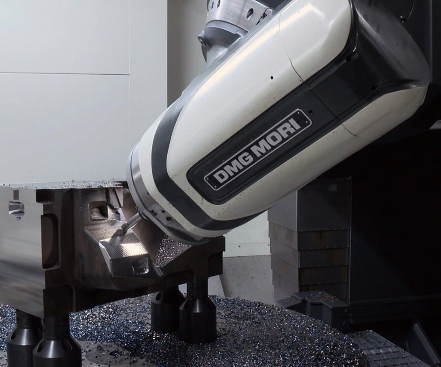
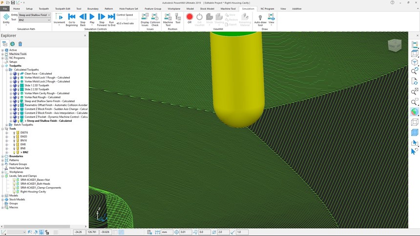
When machining molds, especially large ones, there is an increased risk of collisions involving the machine, cutting tool assembly, workpiece and work holding. PowerMill form Autodesk offers automated collision avoidance routines that can be used to machine parts safely with minimum programming intervention. At the same time, cutting tool length can be minimized to avoid chatter and deflection that could negatively impact surface finish.
There also are some important machining and software elements to consider when striving to achieve the best surface finish. When it comes to the machine itself, consider maintenance and upkeep as well as a solid setup. Without proper upkeep and cleaning, grit can get into smallest of areas within the machine, which can cause hard-to-find vibrations. Vibration is a quick way to kill a good surface finish. And, when cutting with a tiny cutter with tiny stepovers, the rigidity of setup is vital to reduce vibration and save the tool from breakage.
From a software perspective, consider these three toolpath programming tips to the best possible mold surface finish:
- Reduce stepover to as little as possible. If time is not an issue, a stepover of 10 to 15 percent is ideal.
- Pay attention to where chips will go. Watch the cutter simulations and determine where the chips will be flying because cutting over chips is a quick way to ruin a good finish.
- Take a chip. If not making chips, the cutter will be just rubbing on the part, which leads to odd tool marks and a poor surface finish.
Overall, the demands and features of the final part will always dictate the necessary type of mold surface finish. Determining where to make compromises on various part features, as well as on the time and effort involved in moldmaking, also will dictate a lot about surface finish.
First appeared in MTDCNC publication.
Related Content
Hands-on Workshop Teaches Mold Maintenance Process
Intensive workshop teaches the process of mold maintenance to help put an end to the firefighting culture of many toolrooms.
Read MoreMachine Hammer Peening Automates Mold Polishing
A polishing automation solution eliminates hand work, accelerates milling operations and controls surface geometries.
Read MoreHow to Overcome Complex Mold Texturing Problems
Key benefits when considering laser technology for mold texturing and repair.
Read MoreMold Innovations Power Unique Auto Lighting Elements on Hummer EVs
Diamond machining, electroforming of micro-optical inserts and modified latch-lock system help injection molds produce unique forward lighting elements.
Read MoreRead Next
Reasons to Use Fiber Lasers for Mold Cleaning
Fiber lasers offer a simplicity, speed, control and portability, minimizing mold cleaning risks.
Read MoreHow to Use Continuing Education to Remain Competitive in Moldmaking
Continued training helps moldmakers make tooling decisions and properly use the latest cutting tool to efficiently machine high-quality molds.
Read MoreAre You a Moldmaker Considering 3D Printing? Consider the 3D Printing Workshop at NPE2024
Presentations will cover 3D printing for mold tooling, material innovation, product development, bridge production and full-scale, high-volume additive manufacturing.
Read More
