Making the Complex Simple
Tool center point management streamlines five-axis programming and setup.
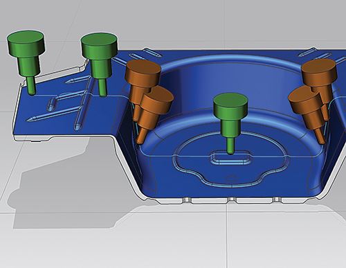
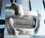
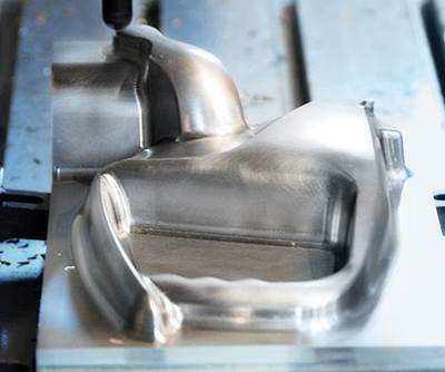
Moldmakers know that a three-axis approach to deep and tall features requires the use of long, skinny tools, but this approach doesn’t work very well. Speeds and feeds suffer because the entire process must be slowed down to accommodate the longer, weaker tooling. This means overall mold-production time suffers as well. Five-axis machining, however, enables the tool body to be tilted away from the contact point, ensuring that the tool does not extend too far from the holder, and permitting the use of shorter, more stable tools when cutting deep cavities or tall-core molds (see Figure 1).
It’s no secret that five-axis technology offers other huge benefits to mold manufacturers. More efficient mold production, improved surface finishes and decreased polishing requirements, to name a few. But what is it specifically about five-axis technology that yields the biggest benefit to mold shops working with deep and tall features? What actually provides the ability to keep the tool tilted in all the varying directions with total control and without the worry of part interference or collision? The answer is tool center point management.
Visualize exactly what is happening as a tool moves around a part in five-axis simultaneous machining, and then try to imagine the types of calculations that are necessary to maintain control during this fluid dance of the tooltip. It doesn’t take long to realize that there is much more going on behind the scenes than what meets the eye.
Tool center point management, or rotary tool center point, is a feature within advanced machine tool controls that significantly simplifies five-axis programming and setup complexity. It makes the program and the part setup independent from machine setup and configuration. Without tool center point management, the programmer has to account for the distance from the center lines of rotation for the rotary and tilting axes, either in the program or in the postprocessor. With tool center point management, the setup is as simple as it is on a three-axis machine, and the control tracks the relationships among the tooltip, axis center lines and part setup.
The Path to Programming Efficiency
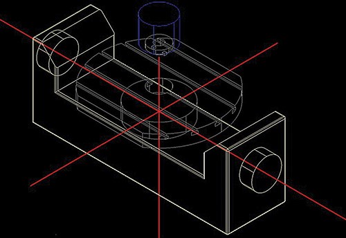
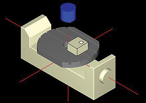
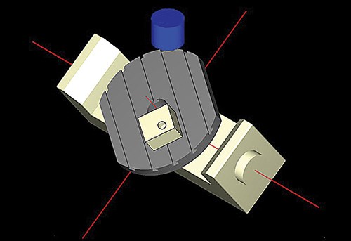
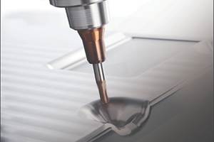
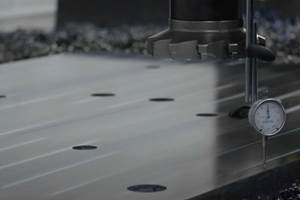
All five-axis machines, regardless of the actual axis configuration, have a fixed mechanical center line for the machine’s rotary or tilting axes, around which each axis rotates (see Figure 2). The machine table surface, workpiece position, spindle gage line and cutting tooltips are all located at some measurable distances away from the center line (see Figure 3). When the programmer performs the machine’s part and tool setup, something needs to account for and track the varying distances as the part is machined, and as the tool and workpiece move throughout the machine’s space (see Figure 4). Before tool center point management was an option, this tracking was accomplished within the CAM program itself. This proved problematic and time-consuming. The machine tool control isn’t smart enough, or advanced enough, to account for the relationship between the machine tool’s kinematics and their relationship to the workpiece and program, so the responsibility falls on the CAM program or postprocessor.
Without tool center point management, the programmer must program all settings from the center line of rotation instead of the traditional workpiece zero point. This means that the solid model must be moved away from the zero reference point in the CAM system the exact same distance as it is physically on the machine tool. Then the program is created with the use of the postprocessor and tested on the machine. If any positional adjustments need to be made, the solid model must be repositioned in the CAM space, the program must be reposted, and the entire process must be repeated as many times as necessary. After all of this, the program will finally be ready to run successfully, and the job can be completed. However, even after all of this preparation is complete, once the workpiece is removed from the machine, this tedious process will be required to complete a future repeat job for that part. The entire process is not efficient.
Tool center point management grew out of the need to ease the implementation and use of five-axis technology and increase its efficiency. Machine tool manufacturers realized that the machine control itself should accommodate all of the machine’s kinematics and movements as well as automatically control the correlation among all necessary data points (machine center line, spindle gage line, tooltip and workpiece zero point). Tool center point management accomplishes these goals.
Better Control and Simplified Setup
Tool center point management makes the entire machining process more efficient, quicker and easier for the programmer and machine operator to complete. It streamlines the programming process. The programmer does not need to wait until the part is actually located on the machine to program the process, because he does not need to account for any machine-related data in the program or postprocessor. This is all taken care of by the software within the machine control.
When the operator sets up the five-axis machine, he simply locates the zero point of the workpiece using an edge-finder or indicator, just as he would on a three-axis machine. He does not need to be concerned with the location of the part within the machine’s workspace. Also, if corrections are necessary, he can simply make the adjustments to the part setup as opposed to altering or reposting the program to make the adjustments. This eases the setup of subsequent runs of this part.
Summary
Although tool center point management was introduced a couple of decades ago, not all machine tools today have this capability. With it, the entire machining process is not only more controlled, but the entire setup procedure is simplified. The program can be posted with all program reference data originating from the actual workpiece coordinate system rather than from the rotary or tilting axis center lines. This means the part setup and part programs are both independent from the machine setup. It also means that part setup can be performed in the same simple manner as it is on a three-axis machine, using the corner of the workpiece with an edge-finder.
Related Content
Tips for Tackling Mold Design, Machining, Cutting Tool and Wear Challenges
Tips for tasks ranging from reducing risk in part design and taking advantage of five-axis machining to refining cutting tool performance and reducing wear with guiding and centering systems.
Read MoreMoldmakers Deserve a Total Production Solution
Stability, spindle speed and software are essential consideration for your moldmaking machine tool.
Read MoreHow to Produce More Accurate Molds and Reduce Rework
Patented micro-milling process for manufacturing steel plate flat and parallel helps mold builders shorten mold build times and increase accuracy.
Read MoreMachining Center Spindles: What You Need to Know
Why and how to research spindle technology before purchasing a machining center.
Read MoreRead Next
Five-Axis Myths
A look at the misinformation that prevents moldmakers from taking advantage of five-axis machining strategies to shorten total machining times.
Read MoreHow to Use Continuing Education to Remain Competitive in Moldmaking
Continued training helps moldmakers make tooling decisions and properly use the latest cutting tool to efficiently machine high-quality molds.
Read MoreReasons to Use Fiber Lasers for Mold Cleaning
Fiber lasers offer a simplicity, speed, control and portability, minimizing mold cleaning risks.
Read More
