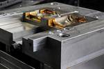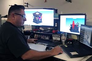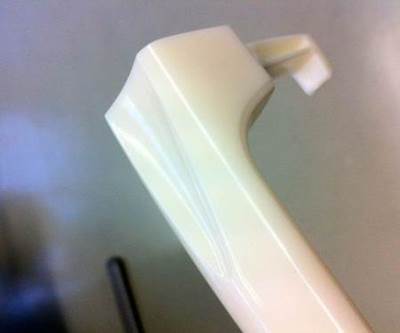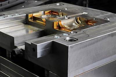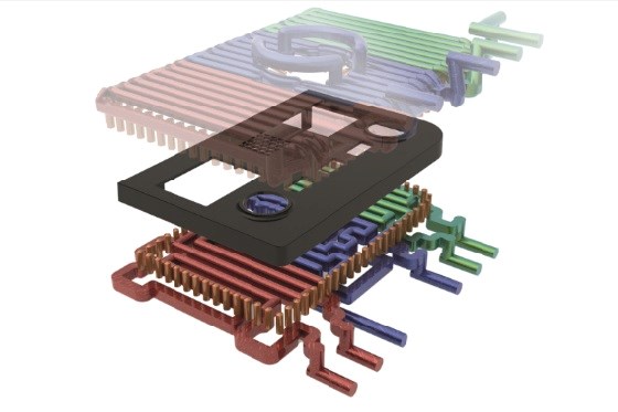
3D CAD view of the conformal temperature control system for injection molding a fascia with a high-gloss surface. Photo Credit, all images: SimpaTec
Skillfully applying process simulation at the start of a project — including designing the best temperature control system and comparing alternative manufacturing methods — can streamline your product development and manufacturing process and provide a part with a high-gloss surface finish.
Undoubtedly, the injection molding of high-gloss plastic parts is very challenging. All it takes for a substandard finish is a mold insert with a poor surface finish, an unsuitable material or the wrong process parameters. For example, the desired level of high gloss may still be achieved by painting the surfaces in a downstream process, but the energy consumed in this painting process contributes to 5-15% of the overall cost of parts manufacture. It’s time to find alternative processes.
For a better interpretation of the absolute values of the shear stresses and the temperatures of the weld lines, use an intelligent, interactive data management platform designed for plastics engineering.
Comparing Variothermal and Traditional Temperature Control
Injection speed, holding pressure and mold temperature influence the quality of high-gloss surface finishes. High mold temperatures can yield ideal high-gloss surfaces, but longer cooling times mean longer cycles. Variothermal temperature control can avoid these longer cycles.
For example, Premec S.p.A., Toolax and Contura MTC collaborated to compare conventional thermal and variothermal control using the same injection mold with conformal cooling for both processes. Figure 1 shows how a customized temperature control system strongly influences the mold wall temperature.
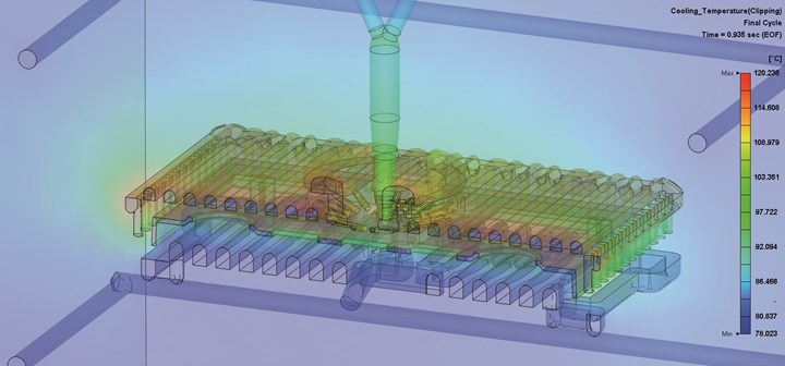
Figure 1. The view of the mold interior in the simulation model shows the temperature difference at the end of the filling stage. Variothermal control on the top side leads to higher mold temperatures than on the conventional temperature-controlled side.
The team evaluated the surface finish of the parts and estimated the cost and energy requirements of both processes while making allowance for any additional painting. They used process simulation to assess whether the molded part’s surface finish could be predicted early in the design stage, making it possible to consider the costs that might arise from a painting process. They also analyzed different materials — PC+ABS and PA6-GF30 (a polyamide 6 (PA6) with 30% glass fiber content).
The PC+ABS reference part produced a high-gloss surface in both process variants. Dynamic alternating temperature control produced an ideal piano-black finish (see Figure 2, right), free of streaks, weld lines and similar defects, and without downstream painting. The conventional temperature control process also yielded a streak-free finish at first glance. However, weld lines were visible on closer inspection (Figure 2, left), resulting in a downstream coating process to achieve the desired piano-black surface finish and thus greater energy consumption. Injection molding with variothermal control also consumes more energy, so how great is the additional outlay?
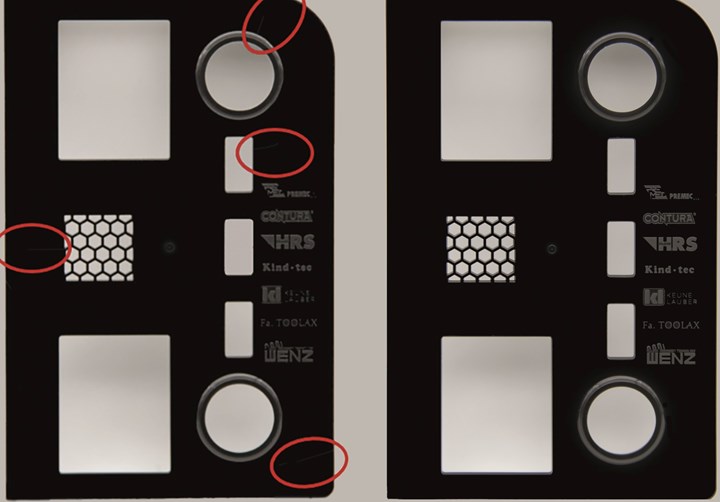
Figure 2. The PC+ABS reference part had a high-gloss surface in both process variants, but weld lines were absent only in the variothermal variant (right).
For both methods, an injection molding machine’s energy consumption was measured, including all additional temperature control units, to produce 40 reference parts. The conventional method consumed 2.882 kilowatt-hours (kWh) throughout the 40 cycles, rising to 7.868 kWh when the dynamic temperature control was added. This represents a 2.7-fold increase in energy consumption. Given an electricity price of 20 cents per kWh (as of 2020), the extra cost per part is just under 2.5 cents.
This is a small increase compared to the downstream painting process needed for conventional mold temperature control, where the extra cost per part for a batch of 25,000 units and a single coat of paint works out at more than 45 cents. That figure excludes handling, possible one-time costs and coating waste of approximately 2%. As a result, the variothermal variant is more cost-effective than the conventional variant (including the outlay needed for the painting process) by a factor of at least 18.
Simulation for Cost Estimation
The team used software to simulate the injection molding process under conventional and dynamic temperature control to determine the true cost of achieving a piano-black finish via variothermal temperature control.
Aside from typical results (flow properties, temperatures, pressure and deformation), the simulation also revealed information about weld lines and shear stresses. The temperature of the weld lines at the time of their formation can be used to determine how pronounced they are. When melt fronts converge at elevated temperatures, the mixing is more extensive. So, the weld lines are less pronounced. In the variothermal variant, this manifests itself on the variothermally controlled side of the part (the visible surface of the top side). The temperature is still so high that the real part shows no signs of weld lines (Figure 2, right).
The simulation revealed the different temperatures of the weld lines. In the variothermally controlled visible surface (top side) of the part, the temperature of the potential weld line is as high as the data points shown in Figure 3, right, indicating that even higher temperatures can be ignored as far as weld lines are concerned. Without variothermal control, weld lines of lower temperatures are formed, which can be detected with the help of the data points in Figure 3, left. Aside from weld lines, it is also important to compare the shear stresses induced on the part’s surface by the two temperature control variants.
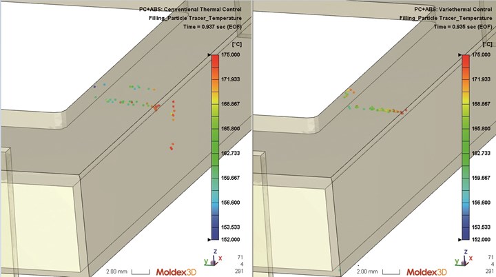
Figure 3. Particle tracking shows the temperature of the weld lines as they form. In the variothermal variant (right), the temperature of the melt fronts on the visible surface (top side) is still so high that they do not show up as weld lines.
The results reveal a visible improvement in the surface finish of the variothermal part but do not guarantee a perfect finish or the elimination of painting.
High Gloss on Glass Fiber
Parts made from PA6 with 30% glass fiber content illustrate the difficulty of achieving a glossy finish without any coating. The finishes resulting from conventional temperature control were so critical that, in some cases, there was no point in considering painting to a high gloss finish due to a lack of feasibility (Figure 4, top left).
Choosing dynamic alternating temperature control managed to produce an acceptable surface finish (Figure 4, top right) that would lend itself to downstream painting and still be capable of producing the desired high-gloss surfaces. Using variothermal control made it possible to produce this high-gloss surface.
The team used simulation to compare the part surfaces, revealing parallels they could use to predict the outcome. For example, the maximum shear stresses at the end of the filling phase in both variants (Figure 4, bottom) and the gradients of the shear stresses suggest a non-uniform part surface. This fact is confirmed in the case of conventional temperature control (Figure 4, left).
The less-pronounced shear stress gradients in the variothermal simulation coincide with a higher quality surface on the real part (Figure 4, right). Similar to the weld line results, the shear stress simulation can also indicate the direction in which the downstream surface quality of the real part is trending. The test on the PA6-GF30 material also highlights how simulation can predict the feasibility of part production.
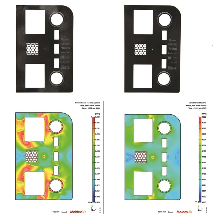
Figure 4. The simulation of the shear stresses (bottom) indicates the direction in which the downstream surface quality of the PA6-GF30 real part is likely to trend — shown here is the higher quality surface produced by variothermal temperature control (bottom right).
For a better interpretation of the absolute values of the shear stresses and the temperatures of the weld lines, use an intelligent, interactive data management platform designed for plastics engineering, which can store information such as model size features, gate sizes, gate types, cooling systems, sampling parameters and CAE simulation results. This step makes comparing subsequent projects a lot easier.
Related Content
Mold Design Review: The Complete Checklist
Gerardo (Jerry) Miranda III, former global tooling manager for Oakley sunglasses, reshares his complete mold design checklist, an essential part of the product time and cost-to-market process.
Read MoreFour Micro Tooling Considerations
Issues involving gating, ejection, mold splits and direction of pull are of special concern when it comes to micro tooling.
Read MoreThree Good Reasons to Switch from Three- to Five-Axis Machining in Moldmaking
Five-axis machining technology is a great tool in the moldmaker toolbox.
Read MoreLeading Mold Manufacturers Share Best Practices for Improving Efficiency
Precise Tooling Solutions, X-Cell Tool and Mold, M&M Tool and Mold, Ameritech Die & Mold, and Cavalier Tool & Manufacturing, sit down for a fast-paced Q&A focused on strategies for improving efficiencies across their operations.
Read MoreRead Next
Tool Up with Rapid Heat/Cool Technology
A rapid heating and cooling technique using pressurized water solves sink, weld line and discoloration problems.
Read MoreHow to Use Diffusion Bonding to Optimize a Mold’s Thermal Performance
Joining dissimilar metals has tremendous potential for conformal cooling, but to successfully use diffusion bonding, a mold builder must understand the complexities of the interface and its effect on the chemical and thermo-mechanical properties of the bond.
Read MoreAdvances in Mold Cooling Simulation
A review of rapid heating and cooling technology as part of the injection molding process and the role of injection simulation software.
Read More

