
Considerations for a High-Feed Milling Strategy
High-feed milling is becoming the chosen methodology for removing as much material as possible in the shortest amount of time, as more shops equip themselves with high-speed CNC machining capability and sophisticated CAM programs.


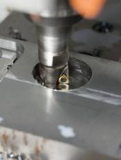
In helical interpolation applications using the HFM method, users can skip pre-machining or pre-drilling. Plus, the high feed cutter has minimal contact with the machine's wall section to provide stable machining.
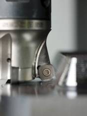
By combining this high-feed cutter with PCBN inserts, production speeds can be significantly increased in cavity milling applications. Images courtesy of Seco Tools.
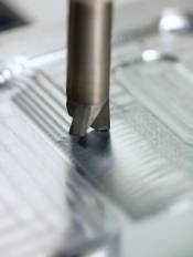
Copy milling using the HFM method is very practical for machining uneven surfaces.
Getting parts out the door efficiently and affordably is a productivity requirement that has remained constant for mold and die producers. In order to remove a significant amount of metal during roughing operations, conventional wisdom of the past has guided shops to choose tools based upon their metal removal rate capacity. This would result in using the biggest tool possible to start the roughing operation and then working down in size until reaching the required shape and finish. Typically, ballnose endmills or button cutters would be employed. However, this methodology can produce a lot of stress that requires a strong robust machining center, hearty workholding and tough tooling.
Plunge milling became another highly favored way of hogging out metal quickly. Plunging transfers the forces axially up into the spindle rather than radially, which can create deflection, loss of accuracy and shorter tool life. An issue with plunging; however, is that the tool is constantly going in and out of the pocket as it indexes to each new position.


High-Feed Milling Basics
Today, as more shops are equipped with high-speed CNC machining capability and sophisticated CAM programs, high-feed milling (HFM) is becoming the methodology of choice to remove as much material as possible in the shortest time. Basically, HFM is a roughing method developed for high metal removal rates to increase productivity and save machining time. HFM uses a smaller depth-of-cut (usually no more than 2 mm), producing a thinner chip that carries the heat away from the cutting edge. It also runs a high feed per tooth: up to five times higher feed per tooth than conventional milling is common. This approach reduces heat generation to extend tool life and provides a higher metal removal rate than normal—over 1,000 cm per minute or up to 200 to 300 percent faster than traditional milling.
The reason for this is that the HFM method takes advantage of small setting angles (45º or less). This produces minimal radial- and maximum-axial cutting forces. Similar to plunging, the cutting forces are directed at the machine spindle in the axial direction, which reduces the risk for vibrations and stabilizes machining. This, in turn, allows for the higher cutting parameters even when machining with a large overhang. And, unlike plunge milling, in HFM the tool stays constantly engaged.
Another HFM time-saver is the number of operations. Since high-feed roughing with its small depths-of-cut generates a near-net shape close to the final requested form, semi-finishing operations can often be eliminated and NC programming is thus simplified. On top of this, the HFM process does not require increased rotational speed from the machine.
Getting Started
To accomplish a HFM strategy, users need to evaluate the overall machining system. Number one is the need for high-speed CNC machining control, high spindle accuracy and thermal stability against spindle growth. Secondly, is the requirement for a CAM software program that can handle toolpath smoothening strategies—such as corner rounding and helical cutting paths. Smooth toolpaths enable a gentle slicing of the workpiece through light engagement conditions while helical cutter movements reduce the cutting impact, energy consumption and cutting forces.
Additionally, the inserts used in HFM are critical. They are thick and have a big radius and strong geometry at the cutting zone. This means you can work at high speed and still have reliable and safe machining. For most HFM operations, trigon-style inserts are preferred over round. The reason is that the main cutting forces are located at the bottom of the cutting edge. Of course, there are situations when you use square inserts, but with a small setting angle.
Typically, this might be required in high-feed heavy roughing applications using powerful machines in stable conditions or in horizontal milling operations, making chip evacuation more effective. But in vertical operations or smaller machines with high rpm, trigon-style inserts are a safe choice, offering excellent chip evacuation.
Applications for HFM
Face milling, especially high volume, with the HFM method is perfect for creating a good platform for further machining operations or a final finishing. In most HFM applications, you’ll often get such close tolerances that only final finishing is needed. Since the work involves large blocks, tools with large diameters are most often used. This means using trigon-style inserts in cutters with cassette bodies. High-feed face milling is relevant for most soft materials.
The HFM method is highly effective in cavity milling, and especially suitable in mold and die. Recommendations for tool choices and other parameters all depend upon what is to be machined, the size of the component to be produced and the level of rigidity. Copy milling using the HFM method also is very practical for machining uneven surfaces.
In helical interpolation, the HFM method is a very suitable solution for making large-diameter holes—you can skip pre-machining or pre-drilling. The high-feed cutter has minimal contact with the component’s wall section. The advantage is more stable machining than with conventional milling cutters that have a 90-degree setting angle.
High-feed machining tools also can be applied to plunging operations. They’re especially appropriate for difficult materials like titanium and other light alloys. HFM is equally suitable for applications with long overhangs. The risk for vibrations drops, which extends the tool life. However, square inserts should be avoided for overhangs larger than 3 x D. Using HFM tools for plunging, however, relies upon normal feedrates used together with larger cutting depths.
Summary
Although HFM is not an end-all, be-all solution, it is a great method to achieve high metal removal, utilize the full capability of today’s machines and achieve long tool life.


Related Content

Tips for Tackling Mold Design, Machining, Cutting Tool and Wear Challenges
Tips for tasks ranging from reducing risk in part design and taking advantage of five-axis machining to refining cutting tool performance and reducing wear with guiding and centering systems.
Read More

OEE Monitoring System Addresses Root Cause of Machine Downtime
Unique sensor and patent-pending algorithm of the Amper machine analytics system measures current draw to quickly and inexpensively inform manufacturers which machines are down and why.
Read More
How to Analyze and Optimize Cutting Conditions to Reduce Cycle Time
Plastic injection mold design and manufacturing company puts NC program optimization software module to the test. The results were surprising.
Read MoreRead Next

Cutting Tool/Software Providers Combine Efforts to Maximize Productivity
Collaboration amongst suppliers to be expert solutions providers is key to a moldmaker’s ability to maximize production throughout their entire manufacturing process—increasing efficiency and productivity.
Read More
How to Use Strategic Planning Tools, Data to Manage the Human Side of Business
Q&A with Marion Wells, MMT EAB member and founder of Human Asset Management.
Read More
Reasons to Use Fiber Lasers for Mold Cleaning
Fiber lasers offer a simplicity, speed, control and portability, minimizing mold cleaning risks.
Read More