Published
The Designer's Edge: Hydraulics
Today I will turn this blog series to hydraulics with a focus on providing a better understanding of proper use and sizing, proximity sensors and limit switches, as well as how tool design and setup in the machine can impact failures in manufacturing.
Randy Kerkstra, Guest Blogger and Tooling Manager

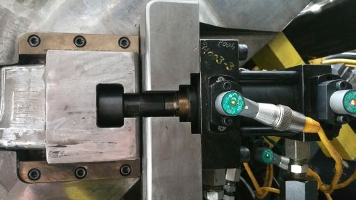
T-slot coupler or connection.
Today I will turn this blog series to hydraulics with multiple posts covering proper use and sizing, proximity sensors and limit switches, as well as the ways tool design and setup in the machine can impact potential failures in manufacturing.
Hydraulics are used for a number of reasons in the injection molding industry, including slides, core pulls, ejection, reverse ejection, gas assist over flows, gas assist valve pins, valve gates, locks and unscrewing molds.
In any situation where hydraulics cylinders are used, set/pull pressures and speed must be understood to avoid leaks and repairs that directly impact downtime. For example, when speed causes impact with a mechanical feature and you are able to “hear” when it is set or pulled, it could result in stress, wear and broken components with T-slot couplers or threaded rod ends.
Options for protecting your components from the negative impacts of speed include adding cushions in the cylinder and having your cylinder bottom out as opposed to your component on the pull direction. On set position your component needs to be home, so you typically do not want your cylinder bottoming out.
In most cases when it comes to maintenance, I prefer to stay away from hydraulics; however, there are a few instances when they are better than mechanical features. If you use many hydraulic cylinders, you have probably experienced oil leaks, so whenever possible I recommend keeping the cylinders off the top of the mold.
Next month I will cover hydraulic pressures in relation to set/pull and cavity plastic pressure.


.jpg;maxWidth=300;quality=90)


