Issues, Trends and Developments in HSM
An overview of the state-of-the-art and future developments in moldmaking using high-speed machining processes for milling applications.
The trend to fully machine parts using high-speed machining technology continues. The implementation of high-speed machining processes can lead to a reduction of overall manufacturing costs for roughing and finishing while maintaining or improving quality. The roughing process holds significant improvement potential with new programming strategies and insert types which allow maximum material removal rates while keeping the residual stock low. For the finishing process, tool dynamics require careful consideration for today's high feedrates and spindle speeds. The following article gives an overview of the state-of-the-art and future developments in moldmaking using high-speed machining processes for milling applications.
Roughing
Changes in Programming Strategies And Process Layout
Although most recent developments in milling technology have focused on finishing, rough machining offers significant improvement potential. The selection of the roughing strategy is predominantly determined by the geometry of the final surface contour. In the past, programming strategies were limited by the capabilities of the programming systems. Modern CAD/CAM systems overcome these limitations and are capable of solving even highly sophisticated programming tasks achieving near net shape results.
Decisions with regard to the two conflicting requirements for the roughing process - maximum material removal rate and near net shape approximation of the final contour - have traditionally been made in favor of the material removal rate because the simple linear programming of cylindrical endmills on stiff and powerful machines allowed high material removal rates. With adequate use of inserts and tooling, rough machining to the final contour with superior quality is possible. The demand to achieve closer and more constant stock heights for the finishing process has resulted in a paradigm change for the roughing process.
Roughing in planes or contour-oriented roughing with smaller tool diameters requires increased effort for programming and creates higher demands on machine tool capabilities. While the maximum spindle power decreases, faster and more frequent changes in direction and acceleration set higher requirements on the dynamics of the axes drives of the machine tool.
Profiting from Alternative Insert Styles
The use of alternative insert types increases requirements for tool definition and rest material calculation in NC programming. By using inserts with round or octagonal shapes, a closer approximation of the final contour can be realized than with cylindrical tools for comparable depths of cut. Cylindrical end mills are still useful for pockets and grooves where an increase of depth of cut results in a lowered stress on the cutting edge.
Considerations for Cutting Forces and Power Requirements
Tool wear of the cutting edge is the most limiting influencing factor when machining tempered steels. Machining tempered steels or hardened materials results in extreme mechanical and thermal stresses on the cutting edges and limits the range of applicable machining parameters. As a result, the stress on the machine tool is kept low. In contrast, when machining softer materials the capabilities of the machine tool (spindle speed, torque and axes speeds) limit the maximum machining parameters such as feedrates, cutting speeds and depths of cut.
For machine selection, the increase in required spindle power for worn tools - up to 40 percent of the original value - needs to be taken into consideration. Experiments have shown that the insert geometry has little influence on the maximum value of the cutting forces, but a stronger impact on the direction of the cutting forces. Passive forces are the highest with toroid geometries - such as toroid, octagonal and pentagonal - while cylindrical endmills show the highest normal forces. Chip forming geometries or positive rake face inserts, which produce beneficial results when machining steels with high adhesivity, do not lower cutting forces when cutting tempered tool steels.
High-Speed Finish Milling
Developments in Cutting Materials And Coatings
Tempered hot working steels with tensile strengths of Rm = 800-1100 N/mm} offer new potential for process improvements.
Micrograin and ultramicrograin carbides for solid body tools and inserts in combination with wear-resistant, multi-layer coatings allow economical cutting parameters that were considered impossible a few years ago.
The significance of coatings is demonstrated by the fact that almost 100 percent of solid body cutters and inserts are offered with coatings. While costs for a modern multi-layer coating are only a small portion of the overall tooling costs, the increase in capabilities is significant. Today, the use of uncoated tools is limited to drilling and tapping applications of light metals.
Machine Dynamics Limit Process Capabilities
In many cases, the machine acceleration is not sufficient to achieve the programmed feedrates during rapid changes of direction. The sudden drop of the machine tool feed rate results in drastically lowered feeds per tooth and tool load. The tool life is significantly reduced and the surface quality decreases due to marks left on the workpiece surface.
Because of these limited machine tool capabilities, developments in cutting materials and coatings do not necessarily result in efficiency increases. Nevertheless those improvements help to achieve higher process stability and extended tool life, both essential requirements for man-less, unattended machining. In addition, surface quality can be improved. Current developments, such as new kinematics and drive concepts with higher accelerations, will enhance the capabilities of available machine tools.
Quality of Toolholder/Tool System Determines Machining Results
Geometrical accuracy depends highly on the stiffness of the spindle/toolholder/tool system, especially when machining deep and tight cavities with challenging ma-chining conditions. High spindle speeds combined with small tool diameters set the demand for small bearing diameters, thus lowering stiffness. In the same way, small machine head dimensions make the use of more stable clamping systems extremely difficult, especially when their maximum spindle speeds are taken into consideration.
One way of reducing the tooling deflection is to minimize the tooling extension by tilting the machining axis moving only three axes simultaneously (3+2-axis milling). In addition, modular tooling systems with exchangeable holder geometries and extensions allow one to adapt the tooling geometry to the specific machining conditions. Despite the increased investment costs for a high number of modules, the number of interfaces should not exceed two to guarantee stability and accuracy of the tool seat. The dynamic characteristics of the milling tool itself also have a significant impact on the machining result. By choosing different material combinations, such as heavy metals for damping effects, the characteristics of the cutter body can be adjusted to the specific needs.
The dynamics of the cutting process are determined by the frequency of the cutting tooth contact. When using long protruding tools with small diameters, one must take cutting dynamics into consideration because of their low stiffness. In conditions with strong excitation, tools can ultimately break. Increasing the cutting speed shifts the excitation frequency to more stable conditions. A variation of the feed per tooth for constant cutting speeds results in good surface quality for the range from 0.03 to 0.07 mm [0.01181 to 0.02755 inches] feed per tooth. In contrast, a clear optimum can be observed for a feed per tooth of 0.07 mm [0.02755 inches] at a cutting speed of 450 m/min [1476 sfm]. The minimum feed per tooth is shifted to higher values.
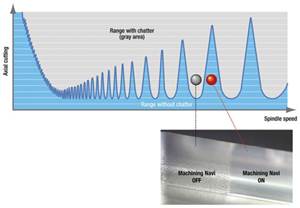
Increasing the depth of cut to values greater than 0.7 mm [0.0276 inch] has a similar impact on the stability of the process. Depending on the cutting speed, a clear range for stable depths of cut can be observed. With a cutting speed of 100 m/min [328 sfm] a change in depth of cut of 0.1 mm [0.00393 inches] is sufficient to cause instability, while at higher speeds a wider range of stable conditions can be observed.
Case Study - Tail Light Mold
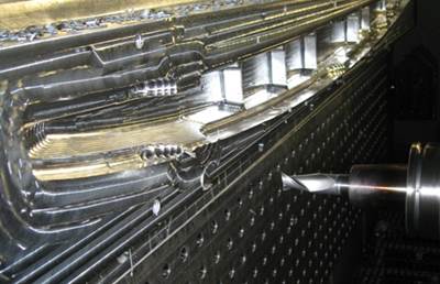
Figure 1 shows an example of achievable process parameters for the machining of a tail light mold. The part was machined using 3+2-axis machining. Using the high-speed spindle it was possible to achieve a superior surface finish and avoid the use of EDM machining. Significant time and cost savings compared to a conventional machining process were realized.
Summary
The implementation of high-speed ma-chining offers significant improvement potential. Increased machine capabilities and developments in cutting tools offer new opportunities not only for the finishing process, but also for the roughing process. For roughing, new insert geometries and powerful programming systems allow one to bring the raw part closer to final dimensions in a shorter time with low tool wear. In the finishing process, paying close attention to the dynamic characteristics of the tool/toolholder system is critical for a successful high-speed machining application. When changing a milling process to high-speed machining it is essential to pay close attention to all process steps in order to gain optimum results. This becomes even more important with future developments in the machine tool and cutting tool industry promising further productivity increases in high-speed milling applications.
Related Content
Advantages and Disadvantages of Copper and Graphite Electrodes
Both copper and graphite provide approximately the same end result, so it is important for a shop to consider the advantages and disadvantages of each material in order to discover what would work best in their shop floor environment.
Read MoreSolving Mold Alignment Problems with the Right Alignment Lock
Correct alignment lock selection can reduce maintenance costs and molding downtime, as well as increase part quality over the mold’s entire life.
Read MoreHow to Eliminate Chatter
Here are techniques commonly used to combat chatter and guidelines to establish a foundation for optimizing the moldmaking process.
Read MoreLaser Welding Versus Micro Welding
The latest battle in finely detailed restoration/repair of mold materials.
Read MoreRead Next
Basic Questions on High Speed Machining
Can HSM apply to turning? Does the “speed” refer to cutting speed or spindle speed? What is the explanation behind lower forces and lower heat generation?
Read MoreReasons to Use Fiber Lasers for Mold Cleaning
Fiber lasers offer a simplicity, speed, control and portability, minimizing mold cleaning risks.
Read MoreHow to Use Continuing Education to Remain Competitive in Moldmaking
Continued training helps moldmakers make tooling decisions and properly use the latest cutting tool to efficiently machine high-quality molds.
Read More


.jpg;maxWidth=300;quality=90)
