How to Achieve Intelligent, Automated CNC Machining
A review of the benefits of automating CNC machining by measuring and automatically changing the cutting tools as they wear during the machining process, and what a moldmaker should consider before investing in such a technology.
Every mold manufacturer is searching for ways to increase productivity, and sometimes that means examining your current processes and changing the way you work. Despite what many think about the dreaded "change" word, if change is implemented properly it can mean less work, not more. An area in which you can experience dramatic results with the right change is doing your finish machining (where the most machine hours are required) through intelligently automating your cutting tool changes.
Barriers to Automated Machining
Many moldmakers run their machines at night or on weekends without an operator present, but when examined a little closer you may discover that this is often not truly automated CNC machining. Some moldmakers set up their CNC machines to run finish cutting operations (after heat treating) and then let them run at night or on the weekend until either the program ends or the cutting tool breaks. If the life of the cutting tool was well tested and known then some moldlmakers may write macros into the code to change the tool after a certain period of time without knowing the condition of the cutting tool. Although this gives a certain level of automated CNC machining, it is still a relatively passive and uncontrolled situation as compared to a truly intelligent and reactive process.
Conditions for Automated Machining
In order to run for a virtually unlimited amount of time with assured accuracy of machining, you need a tightly controlled environment requiring that you automatically control and manage (change) the cutting tools based on actual wear or breakage, and also adjust for the thermal expansion of the machine in real time.
Thermal expansion algorithms incorporated by some machine tool builders are often highly theoretical (or based on spindle temperature versus time running), but are not able to take into account a door being open or the sun shining on the machine. Therefore, to manage this you need to measure the actual position of the spindle relative to all three axes in real—or as close as possible to real—time.
To achieve this, one needs to do the following:
1. Control (measure) the condition of the cutting tool before machining starts for each program.
2. Control (measure) the condition of the cutting tool after machining is finished for each program.
3. Automatically change the cutting tool for a duplicate if measured out of a set tolerance.
4. Stop machining (for a given part ) if a tool break is detected, but be able to continue machining other parts.
5. Control and adjust for thermal expansion of the CNC machine in all three axes after each program has been run.
6. Have the ability to machine multiple parts one after the other (e.g., after one part has been machined then automatically start to machine the next part including automatic selection of programs and cutting tools for that part).
Solution for Automated Machining
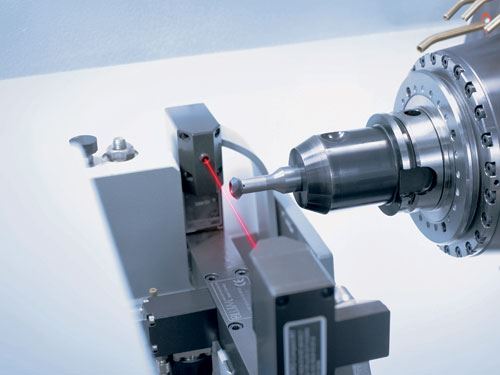
To achieve the aforementioned conditions a combination of software and hardware technology is required—technology that combines sophisticated software, which will process the NC code, and add and control all required tool calls, program calls and algorithms for thermal compensation , with a laser measuring device. The result is fully automated CNC machining achieved by intelligently monitoring and managing the condition of cutting tools during CNC machining. Note that the amount of code required for each program is so large (hundreds of lines) that this not practical to generate manually, one must use a complex program that automatically generates all the required code and algorithms.
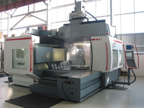
Using such a technology will allow a moldmaker to run a CNC machine for almost an unlimited amount of time without operator intervention. The only true limitation is then the number of parts that can be clamped on the machine and the number of positions in the toolchanger. For example, a large CNC machine (with 60 positions in the toolchanger and a clamping / travel area of 1,500mm x 2,500mm) can run for 50 to 60 hours nonstop on a number of smaller parts or one very large part.
Appropriate Applications and Limitations
It is important to note that this technology is not appropriate for all machining operations or machines. Its ideal use is for finish cutting after heat treating and for operations where the machine will be able to run for at least several hours. This can be achieved by either multiple smaller parts or one large part on the machine.
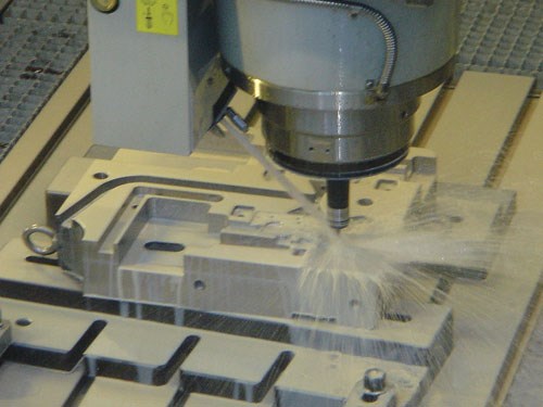
The technology is not appropriate for rough cutting operations where a lot of material is being taken away. It should also be noted that you will need a machine with at least 20 positions in the toolchanger as well a more holders and duplicate tools for this technology to be effective. The more positions the better.
Also to use the technology the user may need to alter the way the NC programs are prepared. Each program will need to have a unique tool id, direction of rotation and rpm for the tool included in the NC code generated by the post processor. In addition, programs need to be broken down into sections that equate to approximate or slightly less than expected or known tool life per tool according to the experience of the toolmaker for the specific type of machining to be performed. Note that for finish cutting hardened steel (46 to 48 Rockwell), an average of 1 hour per tool is a good starting point.
Software/Hardware Breakdown
Following is quick overview of how the technology works. There are many other functions that also need to be considered for such a technology to work effectively—selection of combined tools or separate tools for each part; the ability to rotate programs if the part is clamped at a different angle; copying and editing of programs, etc.
Software
• CAD programs are imported from any CAD system into the program.
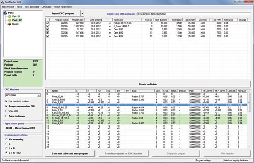
• The software then automatically creates and then expands a tool database from the tool data imported with each program.
• Using user-defined tolerances in the cutting tool database (part of the program), the software automatically creates a tool table with either separate or combined tools (as selected) for each part to be machined.
• The NC programs—including newly generated tool calls and program calls, as well as the algorithm for adjustment of thermal expansion—are sent to the CNC machine in one package of NC code that includes a newly generated TEST and START program.
• A tool setup list is automatically generated that can be printed and used for setup of the toolchanger.
Hardware
After transfer of the data to the machine, all cutting tools are automatically measured in the laser using the TEST program to ensure they are within the required (programmed) tolerance and in the correct positions in the toolchanger. If a tool is measured out of tolerance or in the wrong position it is locked out from machining. A warning appears and the tool can then be changed before machining is started. The caliber is also measured in the laser and the (initial) reference position of all three axes is automatically recorded.
Once all tools have passed the TEST program the operator activates the START program, which then controls all further machining. As each individual program is automatically called up, the appropriate cutting tool is measured in the laser again before machining starts. Once machining of each program has finished, the cutting tool and caliber are measured again in the laser.
If the tool is within set tolerance then the next program is automatically called up; if out of set tolerance then a duplicate is selected and the program is repeated, or if only slightly out of tolerance (value set by user) then the tool is locked out for further use. However, the program is not repeated and the next program with a duplicate tool is called up. All three axes are corrected relative to the measured position of the caliber.
If a tool break is detected, the part is locked out from further machining (to prevent a crash) and machining of the next part automatically begins if there are multiple parts on the machine. Once all parts have been run, the machine automatically shuts down. A report is then generated showing tool wear, compensation of the three axes for each program and locked out tools.
Summary
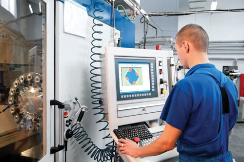
The more that can be prepared in a standardized format off the machine the better (e.g., each specific tool in the plant has a defined rpm, rotation and allowed tolerance, according to what it is used). This can be done with software either in the office or in the plant on a computer next to the machine, but it is important to not allow the operator to play with parameters on an ad hoc basis. All parameters should be standardized and adjusted by one administrator or at least a limited amount of authorized people.
Feedrate should be defined by the person preparing the CNC program and in general not adjusted on the machine by the operator. Note that there is software technology available that automatically optimizes the feedrate and toolpath during machining.
Most mold manufacturers will run smoother, more efficient operations with less mistakes if standard operating procedures are put in place when it comes to machining, and more specifically automating your CNC machining by measuring and automatically changing the cutting tools as they wear (versus only a time limit per tool) during the machining process.
Contributor:
Max Leser is director of Tools + and has been running a modern toolmaking facility that specializes in large and complex tools for die casting aluminum in the Czech Republic for 20 years (www.toolsplus.cz ). Together with Karel Kazak he developed ToolMaster as a solution for automated CNC machining to make use of unused machine time available at night and on the weekends without needing people to be present.
For More Information:
ToolMaster
www.toolmastercnc.com
max.leser@toolmastercnc.com
Related Content
Treatment and Disposal of Used Metalworking Fluids
With greater emphasis on fluid longevity and fluid recycling, it is important to remember that water-based metalworking fluids are “consumable” and have a finite life.
Read MoreMoldmakers Deserve a Total Production Solution
Stability, spindle speed and software are essential consideration for your moldmaking machine tool.
Read MoreThe Benefits of Hand Scraping
Accuracy and flatness are two benefits of hand scraping that help improve machine loop stiffness, workpiece surface finish and component geometry.
Read MoreAdvantages and Disadvantages of Copper and Graphite Electrodes
Both copper and graphite provide approximately the same end result, so it is important for a shop to consider the advantages and disadvantages of each material in order to discover what would work best in their shop floor environment.
Read MoreRead Next
A New Standard for Roughing in Moldmaking
A look at how to use modern toolholding technology with assurance that the cutting tool will not pull-out and how to increase feeds and speeds during heavy roughing.
Read MoreHow to Use Strategic Planning Tools, Data to Manage the Human Side of Business
Q&A with Marion Wells, MMT EAB member and founder of Human Asset Management.
Read MoreReasons to Use Fiber Lasers for Mold Cleaning
Fiber lasers offer a simplicity, speed, control and portability, minimizing mold cleaning risks.
Read More


.png;maxWidth=300;quality=90)


