Design Change Communication Modernized
A look at how CAD comparison and direct modeling technology have improved design change communication processes.
Technology—including CAD technology—has changed dramatically since the 1980s. As soon as new technology is developed, it is integrated into products and our way of doing business. In the manufacturing world, CAD software versions are released at regular intervals with product design and manufacturing processes integrating the new CAD technology as soon as it becomes available. However, even with all this new technology available at a moment’s notice, companies continue to compare and manage design changes as they did in the 1980s. By moving beyond pencils and paper overlays, modern technology tools make finding and communicating design changes easy, fast and accurate, which greatly improves financial gains.
Design changes can happen at nearly any moment in the design-to-manufacture process. How clearly and accurately these changes are communicated—if they are communicated at all—can make or break both product quality and profit margins. The key to success is a consistent, well-defined method for detecting and reporting all design changes.
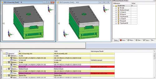
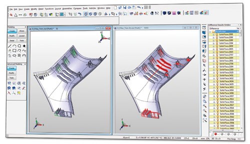
Automated change comparison software offers toolsets specifically designed to quickly and accurately identify any revisions between two file sets of components or assemblies. Mold manufacturers can import a new revision from an OEM, compare the versions, make updates in real time and then re-compare to make sure all of the revisions were made exactly as specified (see Figure 1).
Benefits of Automating Design Comparison
After the initial quoting process is complete and part production begins, any changes introduced can impact the cost to make the product, and changes not incorporated correctly can greatly influence the quality of the finished good. And that’s where consistent, automated detection methods become useful to ensure product quality while reducing costs.
Automated change detection software reduces the fear of missed or inaccurately documented changes by verifying changes quickly and fully, and oftentimes uses graphical means to pinpoint the area where a change exists. The integration of an automated file comparison in a change tracking system means manufacturers can be confident that all changes are found and are incorporated into the design without significant interruption or delay.
Manufacturers have additional financial incentive to verify changes. Changes can require material quantities to be larger, smaller or even require an entirely different material from what was originally quoted. If the product process continues without incorporating these changes into the cost, the manufacturer can be left with reduced, even negative profit. By comparing two design versions, automated change comparison software can help manufacturers breathe easier knowing that they have accurately re-quoted based on design changes, meaning profit margins remain consistent.
Manual design and CAD file comparison can take many man-hours to complete, and still holds the potential for simple human error. When used in a consistent process, design comparison software can save hundreds of man-hours of time. In one case, a customer using design comparison technology claimed that it saved years of combined effort to automatically compare CAD files. Design change software can also provide more assurance that the manufacturer is doing everything possible to ensure quality and a faster time to market, which benefits both the manufacturer and customer in terms of profits.
Direct Modeling Technology for Better Comparison
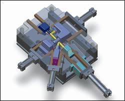
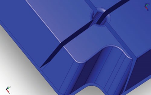
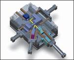
Additional benefits of change comparison software exist when change detection processes work in conjunction with direct modeling CAD software (see Figure 2).
The fundamentals of direct modeling—the ability to work with customer data regardless of file construction or file type—is the first step to allowing users of comparison technology to compare file revisions or design changes using native files. Most direct modelers accept numerous native file types, which mean they rely on file translations with the highest degree of accuracy. And since most companies do not always use the same CAD systems as all of their OEMs or suppliers, using native files means a higher quality file comparison. Comparing native CAD files with production CAD files eliminates the additional worry that file translations introduced unintended changes to CAD file geometry.
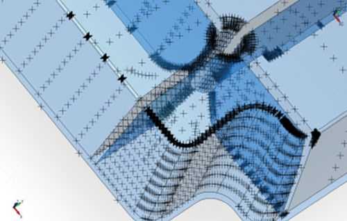
Additionally, direct modelers that rely on geometric comparison of part files also produce more accurate comparison results. Geometric comparison is mathematically a more accurate method to compare files than a points-based method. It checks for geometric congruency and pattern matching, and if not found, alerts the user to the difference. Systems that place point clouds on the surface of models for comparison only compare a sampling of points. The problem is that there is no guarantee all differences are found this way because points-based comparison relies on the proper amount and spread of points. In contrast, the chances for missing any changes during a design review using a geometric comparison environment are greatly diminished (see Figure 3).
Direct modeling also offers flexibility and simplicity, especially for complex assemblies. Direct modelers allow manufacturers to easily manipulate files to isolate areas of a product that—especially in areas of mold design—are important cost drivers. Value-added changes that improve the manufacturability of a design, such as correcting undercuts and improving flow, can be done quickly with direct modeling. Geometry can be changed in direct modeling software regardless of whom or what created the design, meaning these value-added design changes are easy for the manufacturer to complete. Having the ability to interrogate files easier means more accurate job quoting.
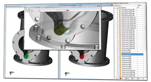
Manufacturers can even rely on their own expertise to suggest improvements to products. During any collaboration process, manufacturers can use direct modeling in conjunction with change comparison software to document IS/WAS product versions (see Figure 4). And as revisions are passed back and forth between the manufacturer and customer, automated design comparison software can be used to track all the changes, confirming the changes that are agreed upon are the ones that enter production.
Considerations before Investing in Change Comparison Software
Change comparison software is ideal for companies that have lost money due to design changes. Ask yourself these questions:
• Have I had to absorb the cost of scrap because we missed a design change and manufactured the wrong part?
• Do we have a consistent, fast and effective method for always catching and verifying all design changes?
• How long does it take to implement the changes throughout the manufacturing environment, and is it an acceptable amount of time?
• Have we received design changes, yet failed to re-quote the job accurately, missing out on potential profits?
If change comparison software finds one change that would have otherwise been overlooked, the software will pay for itself.
Additionally, if you find that you must recreate models instead of reusing original files or need to purchase, maintain and train employees in multiple software packages just to keep up with customer demands, consider comparison software coupled with direct modeling software.
Summary
By modernizing design change tracking and communication with more sophisticated design comparison tools and software, manufacturers can more accurately document design changes throughout the design-to-manufacture process. In doing so, costs related to missed or poorly communicated changes are reduced—e.g., scrap and wasted time. What is gained is a more consistent, well-defined design change tracking process, which will increase profits and product quality.
Related Content
OEE Monitoring System Addresses Root Cause of Machine Downtime
Unique sensor and patent-pending algorithm of the Amper machine analytics system measures current draw to quickly and inexpensively inform manufacturers which machines are down and why.
Read MoreIt Starts With the Part: A Plastic Part Checklist Ensures Good Mold Design
All successful mold build projects start with examining the part to be molded to ensure it is moldable and will meet the customers' production objectives.
Read MoreHow to Analyze and Optimize Cutting Conditions to Reduce Cycle Time
Plastic injection mold design and manufacturing company puts NC program optimization software module to the test. The results were surprising.
Read MoreFour Micro Tooling Considerations
Issues involving gating, ejection, mold splits and direction of pull are of special concern when it comes to micro tooling.
Read MoreRead Next
Software Facilitates Art-to-Part Capabilities
Design/manufacturing software allows moldmaker to produce prototype parts in less than seven weeks—something few moldmakers can accomplish.
Read MoreReasons to Use Fiber Lasers for Mold Cleaning
Fiber lasers offer a simplicity, speed, control and portability, minimizing mold cleaning risks.
Read MoreHow to Use Strategic Planning Tools, Data to Manage the Human Side of Business
Q&A with Marion Wells, MMT EAB member and founder of Human Asset Management.
Read More


.jpg;maxWidth=300;quality=90)

