Verifying Machining Through Simulation
NC verification technology is one of the most useful computer-aided manufacturing tools available to moldmakers, enabling engineers to simulate the machining process of an NC toolpath in order to detect and eliminate errors before machining takes place.
Although NC verification software has been available for more than a decade, recent developments in the technology have catapulted us into a new age of digital manufacturing that is enabling mold builders to be faster, more accurate and more efficient - all while creating higher quality parts with fewer resources. What started as a simple "part program check tool" nearly 15 years ago has developed into a powerful manufacturing software suite capable of entire CNC machine tool simulation, detailed model analysis, fully automatic NC toolpath optimization and a means through which engineers can close the loop on digital manufacturing by creating virtual models of machined parts that can be utilized in CAD systems.
Why NC Verification?
There are many chances for error during the toolpath generation process: the NC programmer can make errors (either manually or by incorrectly using the CAM system); plans can be misread; the CAM system may not correctly create the toolpath program; or the post-processor may not correctly generate the NC machine tool instructions. Because of the potential for error in the CAM process, the NC toolpath should be verified before cutting metal. Not testing new programs risks machine tool crashes, damaged fixtures/holders, broken cutters, loss of productive machining time and even potential injury.
There are generally two types of non-computer toolpath verification available. First, the NC programmer can manually verify the program. This method is relatively useless for anything other than the simplest jobs. Manual verification is time-consuming, error-prone and not practical for today's more complex mold work.
A second method is machining a test prototype part, usually out of some sort of soft material such as foam, wax, wood or renboard. This method requires the NC machine tool to be taken out of production for the test. The shop also must absorb the setup and takedown cost, the labor expense of operator time and the cost of the materials. If a problem is detected, the program must be sent back to the programming department to be corrected. Once fixed, the test cycle starts again. This cycle can cost companies quite a lot, as Supreme Tool and Die (Fenton, MI) learned years ago. Analysis at the shop showed that 15 percent of available machine hours were being used to test new NC programs. "We don't get paid to test new NC programs," notes Joe Glass, senior CNC programmer. After implementing NC software verification into their production environment, they virtually eliminated the wasted prove-out time and freed more than 15 percent capacity of Supreme's existing machine tools. "Not only can we find and eliminate any errors or trouble spots in our NC programs, we send a better, more efficient program to the shop," reports Glass.
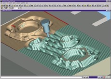
Verifying part programs ahead of time eliminates or significantly reduces the amount of time and money consumed by the traditional part prove-out process. Because mistakes are found before the part program is sent to the shop floor, expensive machine tool resources, materials and operator time are not required (see Figure 1).
The use of shop floor programming introduces a new set of concerns. Often, original customer CAD data must be conditioned or modified for the shop floor programming system and machine operator by an engineer. This is necessary because the original data is not appropriate or the toolpath is cutting something created from the original model, such as inserts or electrodes. Because of the added engineering steps - and added opportunities for error - verification of the toolpath with the original customer model is critical.
Also, shop floor programming systems, by their nature, produce conservative toolpaths. Optimizing feedrates based on the cutting conditions can save significant time.
Analyzing the Model and Verifying the Design Intent
Machining the part virtually has several advantages when it comes to part analysis. Users can zoom in on detail areas and can easily cross-section the model or view it in translucent mode to check areas that would otherwise be impossible to see, such as the intersection of drilled holes.
Measurement tools make it possible to determine the exact dimensions of the final machined part (versus the design model, which can be very different) before the program ever leaves the computer. Users can check wall thickness, volumes, depths, gaps, distances, angles, hole diameters, corner radii, scallop heights and edges.
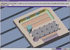
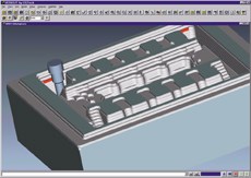
From the time the mold tooling is designed to when it is ready to be machined, the design may have passed through several people, departments, CAD/CAM systems or even companies. It can be difficult to tell whether the toolpath accurately reflects the original design model. Without NC verification software, the only way to be sure is to cut the part and do a first article inspection. But with the software, the result of the CNC machining can be compared to the original CAD design model to detect any differences. Here, the beauty of computer technology embeds the CAD model inside the virtual stock. As the NC verification program simulates the machining, stock is removed as would occur on the real CNC machine. The user can then set a tolerance distance value around the design model. The tolerance can be as tight or loose as necessary. If the cutter encroaches into the tolerance area or comes in contact with the design model, the software highlights the offending toolpath record as an error. Areas with excess material left over from the cutting operation can also be detected. The programmer can then correct these areas in the toolpath before machining a production part (see Figure 2).
Advanced NC Operations: Toolpath Optimization NC toolpath verification also addresses the costs associated with production factors such as machine shop load, excessive machining times, schedule compression, machine and cutter wear and labor costs. By picking the ideal feedrates at which to drive the CNC machine, NC verification software is able to reduce the time it takes to machine parts, improve part quality, minimize machine and cutter wear, and make the entire shop more productive - and more profitable (see Figure 3).
With today's cutting tools, materials and automatic toolpath generation software, it is increasingly critical to use the right feedrate for each and every cut in the toolpath. But determining and setting optimum feedrates presents a number of problems. An incorrect estimate can break the cutting tool, damage the fixture or scrap the part. For that reason, usually only one or two conservative feedrates are used. Typically, the selected feedrates are a compromise between tool life, cycle time and the worst-case cutting condition encountered.
These "worst-case" feedrates are fine for cuts that remove the largest amount of material or encounter the worst cutting conditions. Unfortunately, these slow, poorly controlled speeds waste time, increase costs and create poor cutting conditions elsewhere on the part. Even if the programmer knows the optimal feedrates to use for each cut, inserting them into the toolpath program is time consuming and error prone. Here again, the beauty of software technology makes what was before impossible into a simple reality.
By its nature, NC verification software is a knowledge-based machining system: it knows everything about the toolpath and the changes to the workpiece as the toolpath shapes it. It knows exactly how much material is removed at each and every segment in the cutter path; it knows how deep or wide the cutter is buried in material; it knows the exact angle of cut; it knows upcoming change-of-direction, etc. NC verification software is therefore in a truly unique position to be able to determine the best feedrates for the machining operation.
The program reads the NC toolpath file and divides motion into a number of smaller segments. Where necessary - based on the amount of material removed in each segment - it assigns the best feedrate for each cutting condition encountered. The premise is simple: as the cutting tool encounters more material, feedrates decrease; as less material is removed, the feedrates speed up accordingly. Then, without altering the trajectory of the toolpath in any way, the software outputs a new toolpath with improved feedrates inserted where necessary.
The results can be dramatic. Die Dimensions is a tool and die maker in Kentwood, MI that uses NC verification software to reduce the time it takes to create 3-D form stations for dies. "We optimize the roughing cuts, the first and second semi-finishing operations, and the contour re-machining or 'radius picking' operations [clean-up to remove any remaining material]," says Jeff Abbott, CAD leader. "Our CAM system generates excellent toolpaths, but not very efficient ones. We're able to bring the time spent on air cuts down to a minimum. The result is that we routinely save at least a third off our machining time. On some of our long jobs, this can mean some pretty big savings. For example, after optimizing the feedrates on one program, we're saving about $3,500 dollars worth of machine time on that part alone."
Over the past few years, different software optimization techniques have been developed to best suit roughing and semi-finishing/finishing operations. During roughing, the goal is to remove as much material as quickly as possible. The verification software keeps the cutter at its maximum safe rate of advance into material for the varying cutting conditions. Using the information learned while verifying the toolpath (the amount of material removed by each cut segment), it is able to determine the amount of material removed in each segment of the toolpath and assign the best feedrate. The feedrates are determined using the information supplied by the NC programmer and/or machine tool operator. For example, while roughing a steel mold cavity, material may be removed at a constant axial depth, but the radial width of cut could differ greatly from cut to cut. The software ensures that the feeds are modified to maintain a constant volume removal rate.
In semi-finishing and finishing operations, chip loads typically vary widely as the tool profiles through the roughing cuts and over the contours of the workpiece to near net shape. Here, optimization software considers where the cutter contacts the material and adjusts the feedrate to maintain a constant chip load. The results are improved tool life and higher-quality surface finish. This is especially critical when tip cutting with a ball endmill or when contouring a surface with a small step-over (semi-finishing or finishing in a tool steel mold cavity, for example).
High-speed machining is another area in which feedrate optimization plays an important role. In high-speed machining, the way the cutter contacts the material is critical. Too low a feedrate produces chatter, vibration and work hardening. This leads to poor surface finishes and premature cutter failure. Too high a chip load causes excessive cutting pressure and unsafe conditions that can cause the tool, spindle, fixture or machine to fail. Adjusting feedrates to maintain a constant chip load or volume removal rate helps to reduce these problems and is recommended by cutting tool manufacturers to solve the "chip thinning" problem. Optimization works especially well with high-speed finishing with ball endmills where very small volumes of material are removed at high feedrates and spindle speeds. Spindle speed also can be optimized to maintain a constant surface speed at the maximum contact diameter on the cutter. Depending on the capabilities of the machine, constant surface speed optimization can help improve surface finish.
There is also a certain myth to the whole concept of high-speed machining which NC verification software can help to dispel.
Reduced machining time, improved part quality and less machine and cutter wear are not the only benefits to using NC verification software to optimize toolpaths, according to HS Die & Engineering (Auburn Hills, MI). Says Jack Flietstra, CAM programmer, "We're currently optimizing our roughing cuts, and are in the process of putting it to use for our semi-finishing and finishing cuts as well. We've seen some really good results. One of the benefits that we didn't anticipate is the jump in productivity we got because our machinists can now attend to another job while the machine is cutting at full capacity. They don't have to worry about the exit or entry motions happening at too high of a feedrate and breaking a tool or ruining the part."
Closing the Loop on Manufacturing
Since the invention of the first CNC machine tools, NC programming languages and CAD/CAM systems, manufacturing engineers have needed an accurate electronic model of the initial and in-process state of material. It's difficult to confidently create toolpaths for subsequent operations without an accurate representation of the initial material. The accuracy, efficiency and "correctness" depend on the material's initial geometric shape. Access to the correct geometric workpiece shape in the CAD/CAM environment at each manufacturing stage helps avoid problems when creating subsequent cuts. Until now, the only way to create an in-process CAD model has been with expensive, labor-intensive, error-prone and inaccurate methods.
Today, with NC verification software, a few mouse clicks is all that it takes to export a cut model as an in-process CAD model. Users can create the CAD model at any stage in the machining process, complete with machined features such as holes, fillets, corner radii, pocket floors and walls. The uses for this technology are only limited by the imagination of the manufacturing engineer, and could include:
- Streamlining process planning (planning for multiple setups or staged machining; avoiding problems programming subsequent cuts; eliminating trying to "visualize" the geometric shape of material at each stage of machining).
- Reverse engineering (updating design models or processes to reflect the true finished part; performing mechanical analysis of the "as-cut" part).
- Making use of legacy data (creating CAD models from old APT or G-code programs for updates, modifications or designing mating parts).
This is a brand new technology, but already moldmakers are devising innovative ways to make it work for them. For example, the Nickel Tooling Technology division of Weber Manufacturing Limited (Midland, Ontario) uses a model export program to create castings faster and more easily. Weber designers create large castings for mandrels (master reusable models) to produce nickel shell molds for automotive parts such as instrument panels. Before implementing this program, the process of generating CAD surfaces for these large castings was a time-consuming, labor-intensive process. They used surfacing software on the CAD model to create the casting pattern, but these parts can have thousands of complex surfaces that routinely disappear or collapse while creating the offset CAD surface model. It would often take several days - or longer - to manually trim, delete, offset and repair the surface data.
To improve the process, designers at Weber force the toolpath to undercut in the verification software program and export the part as a casting model. Then they create a toolpath to cut the casting blank. "The first part we tried was an instrument panel casting," says Jurgen Kreisel, systems manager. "We created NC programs that cut the finished dashboard using a 1" ball. We then ran it through the verification software using a 2" ball. This created a 1/2" undercut. We exported it as an IGES surface file of the casting and made the NC programs for the casting pattern. The entire process took less than two hours and no manpower was required, whereas, creating the same pattern manually would have taken a designer several days."
Related Content
How to Fix Predicted Warpage Before It Happens with Windage and CAD Model Morphing
Applying windage and model-morphing techniques saved toolmaker/molder Sturgis Molded Products the time, cost, headaches of multiple part/mold design iteration loops, cumbersome cooling fixtures, and long molding cycles.
Read MoreHow to Generate the Ideal Tool Path for High-Level Accuracy and Finish
When a mold builder can’t compromise part accuracy and surface finish, CAM software with specialized programming strategies is essential.
Read MoreThree Good Reasons to Switch from Three- to Five-Axis Machining in Moldmaking
Five-axis machining technology is a great tool in the moldmaker toolbox.
Read MoreMold Design Review: The Complete Checklist
Gerardo (Jerry) Miranda III, former global tooling manager for Oakley sunglasses, reshares his complete mold design checklist, an essential part of the product time and cost-to-market process.
Read MoreRead Next
How to Use Continuing Education to Remain Competitive in Moldmaking
Continued training helps moldmakers make tooling decisions and properly use the latest cutting tool to efficiently machine high-quality molds.
Read MoreAre You a Moldmaker Considering 3D Printing? Consider the 3D Printing Workshop at NPE2024
Presentations will cover 3D printing for mold tooling, material innovation, product development, bridge production and full-scale, high-volume additive manufacturing.
Read MoreReasons to Use Fiber Lasers for Mold Cleaning
Fiber lasers offer a simplicity, speed, control and portability, minimizing mold cleaning risks.
Read More




.jpg;maxWidth=300;quality=90)


