Tooling Design for Silicone Molding
One of the biggest challenges in mold design for silicone molding is the runnerless molding system or cold deck.
A continuing trend within the molding business is silicone molding, which is being used in the medical, electronics, packaging and automotive industries. The injection molding of silicone has many applications due to the hardness range of the material, from 5 to 90 durometer. All of these industries have witnessed large growth trends in silicone molding—including the multi-material/two-shot molding and overmolding market segments.
Silicone appears to be the material of choice for more and more applications, due to the following properties and benefits:
- Inert, odorless, tasteless, stainless; ideal for medical and food applications
- Hypo-allergenic
- Thermal resistance; special compounds available
- High resistance to weathering and oxidation
- Excellent electrical qualities
- Flexibility and durability
- Colorfast and light stable with FL color pastes
- Can be compounded for special properties
One needs to realize that the technology is 180 degrees opposite of what the experienced injection molder has developed throughout his or her years in the thermoplastics business. Silicone rubbers are synthetic polymers with an alternating Si-O backbone. The molecules will cross link with the addition of a catalyst, such as platinum catalyst silicones. The two parts are mixed in a predetermined ratio, forming a compound ready to be cured.
The silicone molding process is different from that of thermoplastics in a few different ways. To mold a part, thermoplastic resin is heated in the barrel and injected into a cold mold. Typically, silicone molding of a part requires the liquid rubber to be kept cool (5 to 25oC or 60 to 77oF) and then it is injected into a heated mold (170 to 210oC or 340 to 410oF).
Mold Design and Build
The design and manufacture of a silicone mold is different from thermoplastic tooling as well: e.g., tolerances, venting, part ejection and the installation of a vacuum system. Although the tooling design is different, optimizing processing variables such as temperature, pressure and time are essential in both thermoplastic molding and silicone molding. Silicone has the viscosity of peanut butter as it is combined in the A&B components of the silicone. Once the material is injected through the gates, and has experienced shear and is allowed to have contact with the hot surfaces of the mold, the viscosity becomes that of water.
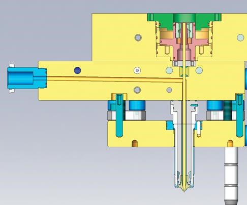
One of the challenges in mold design is the runnerless molding system or cold deck (see Figure 1)—which allows for the equal distribution of material to each cavity at the same hydraulic pressure and consistent temperature profile. (A cold deck is similar to a hot runner system with the exception that it is operating at 60 to 77oF and has cooling channels in it instead of heating elements.)
The cold deck is designed in a way that it will accommodate the temperature differential from the heated mold plates and cavities within the mold to the cooled plates within the cold deck. This is typically accomplished by the use of titanium spacers and insulation board between the cold plates and the heated ones.
The cold water will be introduced to the top plates and then circulated through these plates into the specially designed nozzles to maintain the temperature differential between the cold and heated sections of the mold. The nozzles will have cooling channels in them that are specifically designed to maintain the required temperature at the tip area. This is accomplished by special machining and materials within the nozzles and tip.
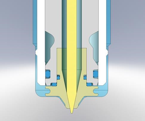
Tips are made of special alloy, powdered metal that is not heat conductive. This allows for close tolerances within the gate area to maintain diameters that are measured in microns (µm) from gate to gate to maintain an equal flow and fill into the cavities. The contact area for the gating insert at the gate area is kept to a minimum of approximately .015-.020 land area to minimize any heat transfer from the hot surface of the mold into the gate area. This will eliminate any preliminary cross linking of the material from taking place.
The design of the tip area allows for the thermal expansion of the mold back into the nozzle well area. The tip area has to have compressibility to eliminate the potential of possibly breaking the gate area out of the cavity area. The gates can be valve gates for when appearance is critical or for sequential molding; or, open sprue type, which allows an open flow of the material into the cavity area. The gates are quite small in relationship to thermoplastics. Typical gate diameters may range from .006 to .020 inch to create the shear required in the silicone (see Figures 2a, b).
Open cold runners are typically filled with high injection speeds to ensure that filling will be even. Cold runners with valve gates allow for a slower filling speed, while with liquid silicone rubber (LSR) the flow velocity is faster in the cavity at the center of the flow than at the surface, thus the material is cross linking as it has contact with the hot surface. Valve gates will be opened at approximately .1 to .3 seconds before injection forward to allow for the silicone to start the shear process as it is injected and to eliminate any compression in the material as it is injected.
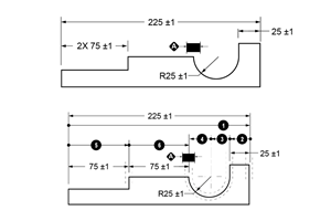
To ensure equal opening and closing of the valves it is imperative to use either a hydraulic/pneumatic or possibly a magnetic valve assembly to assure the positive opening and closing of the valves at the same time. For high cavity, close-pitched systems of approximately 12-mm spacing, it is recommended that either a hydraulically-activated, valve pin plate or a cam-activated system be used to maintain the accuracy of the valve open and close (see Figure 3).
The benefit of using a valve gate system over another type of runner system is that this process allows for 100 percent of the molded product for the material used versus the generation of scrap runners. It has to be remembered that the processor is striving to get a finished part out of the mold without any secondary trimming or secondary runners. Besides achieving better control and optimum cycles combined with lower costs and a better product, you are not contributing scrap to a landfill. Once silicone is processed it cannot be recycled back into the melt stream. The material is typically sent to a landfill. Should you be fortunate enough to find someone who will take it back, you will have to pay $0.15 per pound for it to be taken away and ground up. At this time there is little demand for the regrind, which is why it goes into a landfill.
Summary
Silicone is a material that is driving innovation not only for medical parts, but also for electronic, automotive and soft-touch applications. With further development of self-adhering, chemically bonded silicone, the opportunities for multi-material applications will continue to grow. To gain the knowledge of how your application will perform, it is always recommended that a prototype mold be built to determine the amount of exact shrink and gate sizes that will be right for a specific application. A typical approach is to develop a standard prototype mold frame with quick-change locks to accept a variety of cavity configurations that will fit into the nozzle pitch area. Silicone molding will be a learning process if you are going from thermoplastics to silicone, but with some knowledge and education there can be tremendous opportunities.
Related Content
Tolerancing in Mold Design, Part 1: Understanding the Issues of Conventional Bilateral Tolerancing
Mold designers must understand the location, orientation and form limitations of conventional tolerancing before changing to another dimensioning system.
Read MoreHow to Manage Wall Thickness Changes in Your Mold Design
To ensure even filling and cooling, consider wall section transitions, corners and fillets, ribs and bosses, lip and rim designs and CAE flow simulation software.
Read MoreTolerancing in Mold Design, Part 2: Using GD&T to Address Conventional Tolerancing Issues
Mold designers can achieve a single interpretation of workpiece functionality when following the American Society of Mechanical Engineers Geometric Dimensioning and Tolerancing standard.
Read MoreWhat is Scientific Maintenance? Part 2
Part two of this three-part series explains specific data that toolrooms must collect, analyze and use to truly advance to a scientific maintenance culture where you can measure real data and drive decisions.
Read MoreRead Next
Reasons to Use Fiber Lasers for Mold Cleaning
Fiber lasers offer a simplicity, speed, control and portability, minimizing mold cleaning risks.
Read MoreHow to Use Continuing Education to Remain Competitive in Moldmaking
Continued training helps moldmakers make tooling decisions and properly use the latest cutting tool to efficiently machine high-quality molds.
Read MoreHow to Use Strategic Planning Tools, Data to Manage the Human Side of Business
Q&A with Marion Wells, MMT EAB member and founder of Human Asset Management.
Read More


.jpg;maxWidth=300;quality=90)


