Saving Money with Gas-Assist Analysis
How to use simulation results to save money.
Gas-assist technology simulates the gas-assisted injection molding process, where gas is injected into the polymer melt. Gas-assist simulation was developed about 15 years ago. In the last two years, the technology has evolved dramatically with the introduction of full 3-D analysis. The gas drives the polymer through the mold cavity to complete mold filling and create a network of hollow channels throughout the component. Using gas-assist technology, you can determine where to position plastic and gas entrances, how much plastic to inject prior to gas injection, where to place gas channels, and how large to size them.
With ever-increasing capabilities, a question remains for tool builders: How do I use the simulation results to save money?
Inputs
Before the results are addressed, let’s determine what is required to perform an analysis. If you have had any analysis performed in the past, you know that you need a CAD file and a specific material to get started. For gas assist analysis, you also will need to define the gas injection process method—whether the molder is using gas volume control or gas pressure control. The analysis provides the flexibility of where to gate the part and where to inject the gas. We also must define when to inject the gas based on the percentage of the cavity volume filled.
Gas-assist technology simulates the plastic injection phase, with melt filling the cavity partially or completely as required. Process conditions, runner and cavity flow balancing, and material selection can all be optimized through this analysis.
Once the polymer injection phase is complete, analysis of the gas injection phase begins at a user-defined time or cavity fill level. The technology predicts the location of gas blow-through of the polymer flow front during fill, which results in short shots and unacceptable part quality.
Independent gas and polymer injection locations can be selected. The simulations indicate pressure increase or decrease during the injection phase, followed by the gas pressure history as gas expands into the melt.
Results
With so many inputs to control, getting useful results really depends on what you want out of the analysis. Savvy companies spend a lot of time upfront working with customers to define the objectives of the analysis. When success has been achieved in the past, companies can save time by focusing on particular needs. Very few projects have the exact same needs, but there are some common themes among gas assist projects.
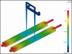
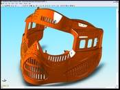
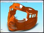
Optimizing gas injection locations is the most frequent objective for tool shops. It’s important to adjust the number and location of gas injection points to achieve a particular wall thickness or part weight. The gas injection pressure and timing have a tremendous impact on the shape of the gas penetration. The illustration in Figure 1 allows customers to review the shape of the gas inside the cavity.
When the gas injection location is fixed by the part design, a common objective is defining the gas injection process to minimize part weight. At this point, users also can define the point at which blowout occurs.
Savings and Benefits
As with most simulation tools, the cost savings comes in the form of minimizing cycle time and material usage. For tool builders, there is the added savings of knowing you won’t have to change gating for the plastic or the gas after the tool is built. With the wide range of results available, it is essential that you know what you want out of the analysis before you start.
Other objectives for which you might consider using gas-assist simulation include:
- Properly sizing gas channels for optimal filling and gas penetration
- Determining the best gas channel layout to control gas penetration
- Injecting gas through multiple gas pins simultaneously or at varying times
- Detecting inadequate gas penetration and proper shot size to avoid gas blow-outs
- Determining gas pressure to avoid short shots
- Optimizing injection speed
- Determining injection pressure and clamp force requirements
- Incorporating delay time prior to inject-ing gas
- Establishing final part weight after gas injection
- Estimating final wall thickness after gas penetration
Summary
Gas-assist analysis is an economical methodology to simulate plastic injection in applications that utilize injected gas into polymers. Companies can save time and money by using the technology early in the design phase to predict material flow, select optimal polymer injection locations, and determine pressure values. Implementing these measures prior to the actual injection process on the shop floor, companies can save significantly on cycle time and material usage once the injection process is completed.
Related Content
Technology Roundup: New/Improved Technologies You Don't Want to Miss
With all the technology joining the market, moldmaking is a versatile, ever-evolving industry. As such, this technology roundup has no specific theme — it features a variety of products for applications and solutions across the industry.
Read MoreCT Scanning Helps Micro Molder Reduce Cost of First Article Inspections
CT scanning services performed by 3D ProScan, a division of NyproMold Inc. provides MTD Micro Molding with accurate, high-resolution internal and external measurements performed about seven times faster and at significant cost savings.
Read MorePrecision Meets Innovation at IMTS 2024
After attending IMTS, it's clear that the integration of advanced technologies is ready to enhance precision, efficiency and automation in mold manufacturing processes. It’s a massive event, so here’s a glimpse of what the MMT team experienced firsthand.
Read MoreThe In's and Out's of Ballbar Calibration
This machine tool diagnostic device allows the detection of errors noticeable only while machine tools are in motion.
Read MoreRead Next
ASH Industries Relies on CAE Services for Production Advances
CAE simulations and Mold-Vac units help bolster quality and customer satisfaction.
Read MoreBringing Greater Process Control to Moldmaking
Advances in machine accuracy, on-machine probing technology and non-contact toolsetting provide powerful tools for automating and speeding mold machining.
Read MoreDoes Your CAD System Support Design and Validation In One Window?
Implementing one tool that can handle part design, mold design, part structural analysis and mold filling analysis is becoming a necessity for today’s mold shops.
Read More


.jpg;maxWidth=300;quality=90)
