Reduce the Time and Costs of Jig and Fixture Manufacture
When it comes to the manufacture of jigs, fixtures and assembly tools, time-to-market for new products can be reduced, overall costs can be saved and the quality of the resulting components/production can increase with the use of additive fabrication—laser sintering and fused deposition modeling.
Additive fabrication—often referred to as rapid prototyping—is a group of technologies that grows products layer by layer. This way of producing parts has two major advantages: (1) there is no need for any product-specific tooling; the only thing that is required is a 3-D CAD design and (2) the almost unlimited part complexity that can be made. Parts that are impossible to injection mold can still be produced using these technologies; however, additive fabrication is very slow compared to injection molding once an injection mold is available. These features make additive fabrication an ideal technology to manufacture components in low volumes.
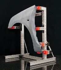
Over the past few years, there have been tremendous improvements in process stability and accuracy, while the mechanical performance of the materials available for additive fabrication has increased substantially. The result is that more and more end use products are made in this way. This article describes the use of additive fabrication for the manufacture of jigs, fixtures and assembly tools (see Figure 1). It shows the unique properties that make this technology attractive for these types of products through two examples.
Technologies Used
For the purpose of jigs, fixtures and assembly tools, laser sintering and fused deposition modeling (FDM) are most commonly used. On an occasional basis, stereolithography is used for its accuracy, but the mechanical performance of laser sintering and FDM is superior to stereolithography resins, which makes the latter less attractive for applications where mechanical loads are applied to the tools.
The choice between FDM and laser sintering is often based on the preference of the end user, although most prefer to produce larger fixtures with FDM because of its intrinsic higher accuracy for large components. In all additive fabrication technologies the durability of the parts made is largely dependent upon their design. As with the injection molding of a specific plastic, it is important that some design rules for additive fabrication are respected when designing a component. As long as these specific engineering rules can be applied, the resulting components will be durable enough to perform their function.
Example 1: Drill Guide Automotive Accessory
The first example comes from the automotive accessory aftermarket, where devices are integrated in cars. Examples are parking sensors and speakers for car audio systems. Growing quality expectations from the consumer dictates that the correct tools are used to integrate these devices into the car in the optimal way. A good tool for doing the job is a drill guide that has a unique fit to the component in which the device will be integrated. Given the variety of car models and the limited number of installations compared to the OEM market, there is a need for a wide variety of these drill guides, while only limited quantities of each of the drill guide designs are required.
Until a few years ago, manufacturing these types of guides was very expensive. Additive fabrication now offers an ideal route for producing these guides if required in small quantities. Both laser sintering and FDM comply with the expected tolerances. In both technologies tolerances of ± 0.3% can be achieved. Also durability is not an issue, as the guides can be engineered taking the specific design rules for additive fabrication into account. The freedom of part complexity is an added value since it doesn’t add costs to the guide. The manufacturing cost of a simple or a complex drill guide will be virtually the same. An additional advantage of additive fabrication is that the materials (typically PA and ABS) are gentle materials when brought in contact with other components. When positioning a drill guide on a high quality surface (like a high gloss lacquered bumper) it is important not to damage this surface.
In this example, a step further was taken. Drill guides for four parking sensors in a rear bumper were needed to be developed. In this case no CAD drawings were available; so the bumper was scanned using a white light scanner. On the point cloud data, the position of the sensors was defined. The point cloud data was then converted into an STL file format (standard file format for additive fabrication) and a guide for each sensor using 3-matic—an STL based CAD system—was created.
Since the guides only needed to be manufactured through additive fabrication, there was no need to go through a time-consuming reverse engineering stage to get the point cloud data into a CAD system. This not only shortened the leadtime for guide manufacture, it also reduced the overall cost. In the guide, specific features in the bumper were used to position each of the guides in a unique way (see Figure 2).
Example 2: Measurement Fixture
The second example is the use of additive fabrication for the fabrication of measurement fixtures. The product development of many (plastic) components involves the creation of quality control tools and methods. In the automotive industry in particular, quality control is an essential part of product delivery. It often means that the component is measured on a CMM to prove that the components (or batch of components) have dimensions within the specified tolerance fields. To perform an accurate CMM inspection of plastic parts, it is often mandatory to mount the part on a fixture that holds the component on predefined points in a specific location (RPS points). Measurement fixtures are particularly essential when the components are flexible.
What we often see, is that the development and manufacture of measurement fixtures is postponed until final production parts are available. There are two reasons for this:
1. It is too often forgotten that plastic parts need proper fixing before a decent quality control (e.g. CMM inspection) can be performed. If a component is not properly fixed, it may deform or it may just perform differently from when it is placed in its final assembly position (and this is the moment when the real quality of the component becomes visible).
2. The cost of measurement fixtures. These fixtures are not cheap. But even more important than the cost of the fixture itself is the cost of modifying the fixture. If a design change to a component is required after the measurement fixture has been manufactured, the cost of modification may end up in the same order of magnitude as the manufacturing cost of a new fixture.
Thanks to additive fabrication, it is possible to make measurement fixtures during the design process of the component. This means that in an early design stage, quality control can already be performed and potential design issues can be tackled.
An example where additive fabricated measurement fixtures really show their value is a car door seal. The door seal is a TPE-injection molded component. In order to perform quality control on such a component, a measurement fixture is required to support the component in an adequate manner. Originally, this was performed in a simple way, by clamping the part on three points (as is conventionally done). The measurements of the component subsequently showed that all the dimensions of the parts were within tolerance. In fact, it appeared that the manufacturer had done a very good job, that’s until the component was mounted on a car and rain tests were performed. These tests showed that there was leakage of water in the corner where the sealing element was mounted.
The problem had to be investigated. A new measurement fixture was made by using additive fabrication. When talking about making measurement fixtures using additive fabrication technologies, a prominent question arises: Are additive fabrication technologies accurate enough for these applications?
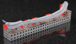
By limiting the size of the locators (contact points) and combining the locators on a modular beam structure, the required accuracy of ±0.05 mm can be achieved. Thanks to additive fabrication, the complexity of the fixture was not a concern. So it was decided to integrate snap fits in the fixture, in the same way that they are used in the car assembly. The fixture (Figure 3) was made using laser sintering. The snap fits perform like a standard plastic snap fit. Mounting the door seal on the newly designed fixture showed torsion in the component. With this information, the product developer could make modifications to the component to eliminate the torsion.
The advantage of using additive fabricated fixtures in this example is obvious. Thanks to the freedom of complexity in laser sintering, it is possible to integrate the snap functions without extra cost. Of course, the fixture requires some engineering, but because the engineer does not have to worry about manufacturability of the fixture, the engineering cost is limited.
Apart from cost, another advantage is the throughput time to make such fixtures. The engineering and fabrication of the fixture takes only two working days. Within less than a week, a representative fixture is available on which quality control can be performed. On top of that, a modular approach to fixtures was chosen, which means that if a design change occurs in one area of the component, only one or a few fixture locators need to be re-engineered and produced in laser sintering. This allows the customer to co-develop the product and the quality control tools, which eventually results in a shorter time-to-market and an increased accuracy.
Conclusion
Additive fabrication is an ideal technology to make jigs and fixtures. Due to the freedom of complexity, technologies like laser sintering and FDM enable a high degree of functionality to be integrated into a single component, with the added bonus that the engineer doesn’t have to worry if this component can be made. The low engineering risk and limited costs associated with typical jigs and fixtures being created by additive fabrication results in their use from an early design stage. By doing so, time-to-market for new products is reduced, overall costs are saved and the quality of the resulting components/production will increase.
Related Content
How to Eliminate Chatter
Here are techniques commonly used to combat chatter and guidelines to establish a foundation for optimizing the moldmaking process.
Read MoreMachining Center Spindles: What You Need to Know
Why and how to research spindle technology before purchasing a machining center.
Read MoreMoldmakers Deserve a Total Production Solution
Stability, spindle speed and software are essential consideration for your moldmaking machine tool.
Read More6 Ways to Optimize High-Feed Milling
High-feed milling can significantly outweigh potential reliability challenges. Consider these six strategies in order to make high-feed milling successful for your business.
Read MoreRead Next
Additive Fabrication Technology
Why you should be aware of it and where it’s headed.
Read MoreAre You a Moldmaker Considering 3D Printing? Consider the 3D Printing Workshop at NPE2024
Presentations will cover 3D printing for mold tooling, material innovation, product development, bridge production and full-scale, high-volume additive manufacturing.
Read MoreReasons to Use Fiber Lasers for Mold Cleaning
Fiber lasers offer a simplicity, speed, control and portability, minimizing mold cleaning risks.
Read More


