Putting More Engineering into Your Mold Design
How to choose the right software to assist you with engineering.
So, you have decided to put more engineering into your mold designs. Rather than seat-of-the-pants engineering and educated guesses, you decide to calculate forces, deflection and distortion, stresses, thermal expansion, runner sizes, turbulent flow for cooling, laminar flow for hydraulic systems, and much more. Where do you start?
It might sound overwhelming, but it doesn’t need to be. The first thing you should do is decide what level of detail and accuracy you need, then choose the type of software that delivers what is important to you.
Products available today can broadly be categorized as calculation-assist software, which allows you to evaluate important design parameters, and finite element analysis (FEA)-based products, which solve more complex problems.
For example, if you want to know pressure loss through a waterline then calculation assistance may be a good solution, if want to know the cycle time reduction based on cooling im-provements then FEA would be more appropriate.
Selecting Calculation Assistance Software
Not all problems require the expense and complexity of FEA software. You can calculate many common mold design problems with programs that only require you to enter sizes, forces or other known quantities, including the following:
- Reynolds Number to determine if your flow rate is turbulent or laminar. (Turbulent flow is important in cooling because it increases heat transfer. Laminar flow is important for hydraulic systems, so that the oil doesn’t absorb too much heat, which causes the oil viscosity to deteriorate).
- Pressure lost through a waterline, bubbler, hose, cooling passage, etc.
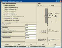
- How much a leader pin (core pin, ejector pin, etc.) will bend when a load is applied.
- The thermal expansion for various materials that go through changes in temperature.
- How much a screw, or any item in tension, will stretch.
- The gallons per minute of hydraulic oil required to activate a hydraulic cylinder.
- The amount a cylinder or cavity will expand due to internal pressure.
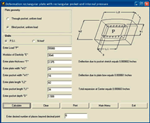
- How much will a mold plate for a side action mold expand and deform due to molding pressure.
- Trigonometric, electrical, production and machining problems and much more (see Figure 1).
Basically they are the problems that you can solve with a calculator, if you know or have time to find and solve the equations. This type of software organizes what a mold designer might have in his notebook binder and then automates the calculation, which reduces the risk of error.
This software acts like an intelligent calculator to solve deflection and stress in common geometric shapes (e.g., mold plates), long column buckling (e.g., ejector pins), and expansion and compression due to loading. Thermal expansion constants for various materials are available, as well as the ability to calculate the initial size, final size or the total expansion. You also can determine runner and gate sizes and shop calculations, such as effective cutting diameter, trigonometry, tooling ball dimensions, roll dimensions, etc.
These packages are very easy to use and require no training. They eliminate the drudgery and potential for errors, compared with manual calculations. Simply choose the type of calculation you want, enter the information required and press calculate. The answers appear in a flash. They also can be a great source of reference information, such as hot runner checklists, galvanic tables, screw thread properties, three wire measurements, unit conversions, gate and runner sizes and material properties.
Calculating software is often used to check the output from an FEA package to make certain that the results make sense. For instance, while looking at the results of a cooling analysis it was noticed that there was only one Reynolds Number shown for a water bubbler inside a core pin. It was then asked, “Is that the inside of the bubbler or the outside?” Using the calculator software, the flow rates shown on the FEA images were used to calculate the Reynolds Number inside the bubbler, calculate the equivalent hydraulic diameter between the bubbler and the drilled hole in the core, and finally the Reynolds Number of the area outside the bubbler.
Whatever your engineering calculation software requirements, choose the option that performs the type of analysis you need. Look at the training required and support needed, then after being shown that the software delivers what you need, use it.
Over-designing your molds is expensive, under-designing is more expensive and often disastrous. Under-design often results in a mold failure, and not all of them are repairable. Molds are occasionally designed and built where the plates are not strong enough to withstand molding pressure. This is particularly true of “A-side” side-action molds, which results in flashed parting lines. Using the improper sizes for bubblers and holes results in unnecessary pressure losses or poor cooling, and can increase the cycle time.
FEA Software
FEA provides the most sophisticated method of solving complex engineering problems. While FEA software covers a wide variety of solutions, structural and plastics analysis packages solve the majority of mold-related problems.
Typical structural problems might include calculating the deflection of a complex mold plate or the fatigue life for tall core inserts. Plastics analysis packages cover everything from evaluating the cooling layout efficiency, runner and gate design as well as filling packing and warpage.
For many analysis projects much of the difficulty and drudgery of early FEA programs has been eliminated. This involved building a finite element mesh and setting up initial conditions. For example, with some of the FEA products, the user never creates a finite element mesh, yet can analyze the cooling layout, runner and gate location and sizing as well as part filling, cooling and warpage.
The software reads part files indirectly in many native formats. The cooling and runner layout can be read in using centerline data from the tool design or created directly within the FEA package. There also are design wizards that provide basic layouts with minimal user input. These can be useful for simpler designs or for initial analysis.
The same can be said for many structural analysis packages: often they do not require extensive knowledge of meshing or FEA. All of this software now runs well on typical PCs although extra memory is often beneficial.
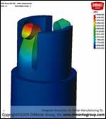
Some of the more sophisticated solutions even couple the plastic and structural analysis for complex solutions to questions such as how much a core will deflect under injection pressures (see Figure 2).
Evaluating FEA Software
In the old days a software supplier might have actually charged you for a demonstration or evaluation of their software. Today you can often evaluate software or have software vendors help you solve real-world problems at minimal or no cost.
If you need a more in-depth evaluation perhaps a consultant will be your best bet. Consultants understand the software and your application. If you explain upfront that you are trying to evaluate software as well as solve a design problem then the consultant can be sure to go into some detail as to the methods used as well as the solutions.
Can you clearly state where you need help? This may take some soul searching. You may have to admit some weaknesses or lack of understanding. The best way to do this may be to look at molds that have been particularly difficult to design or build, or worse yet ones that have had problems. One of the shortcomings with this approach is that if you have designed good tools based on your experience or there have not been significant problems, you may not understand how you could have done better.
In evaluating software it is important that you see your actual problems solved as well as see a typical canned demo. The generic demo can help you understand the breadth of the product capabilities and a more detailed demonstration will help you understand how to solve your real-world problems.
Conclusion
In the last 10 years engineering tools for the mold designer have become much less expensive and the need to use these tools to be more competitive is imperative. The minimal expense of calculation-assist software should make this an easy decision. Due to their expense, FEA tools will require more thought and justification. Given the relative ease-of-use and broad range of problems solved maybe the time is right for your company to invest in these tools. Next year might be too late.
Related Content
How to Analyze and Optimize Cutting Conditions to Reduce Cycle Time
Plastic injection mold design and manufacturing company puts NC program optimization software module to the test. The results were surprising.
Read MoreTolerancing in Mold Design, Part 2: Using GD&T to Address Conventional Tolerancing Issues
Mold designers can achieve a single interpretation of workpiece functionality when following the American Society of Mechanical Engineers Geometric Dimensioning and Tolerancing standard.
Read MoreTolerancing in Mold Design, Part 1: Understanding the Issues of Conventional Bilateral Tolerancing
Mold designers must understand the location, orientation and form limitations of conventional tolerancing before changing to another dimensioning system.
Read MoreTips for Tackling Mold Design, Machining, Cutting Tool and Wear Challenges
Tips for tasks ranging from reducing risk in part design and taking advantage of five-axis machining to refining cutting tool performance and reducing wear with guiding and centering systems.
Read MoreRead Next
Breaking the Mold in Mold Development
Integrated analysis capabilities streamline mold design.
Read MoreReasons to Use Fiber Lasers for Mold Cleaning
Fiber lasers offer a simplicity, speed, control and portability, minimizing mold cleaning risks.
Read More
