Machine Tool Probing for Moldmaking
It’s time to look at the probe as a device that can literally be used as a Virtual Operator to perform many of the everyday, time-robbing processes that eat into your profitability.
As any reputable mold shop will tell you, one of the more revenue-draining processes on the shop floor is inspection of mold base, electrodes and core/cavity inserts—three major components of mold production that all can mark the end of profitability for a job.
For example, machine a base pocket off center or out-of-square and you’ll chase the problem for the rest of the project, and with many customers requiring “interchangeable” components mold-to-mold, you may be talking with your base manufacturer sooner that you like. Carve out 200 cavity electrodes with an error on one electrode and the entire cavity could be off for rework or scrap.
With hard milling being one of the most popular and efficient methods for finishing core/cavity sets and negative stock finishing gathering momentum (milling cavity shut off to 0.0000 and core to -.0005 to reduce/eliminate hand work), the emphasis on accurate setup, CAM verified programming and flawless execution is as great as it’s ever been.
In most shops, these three components rely heavily, and many times exclusively, on CNC equipment. Gaining control over the hardware and processes that control that equipment—programming accuracy, machine selection, fixturing requirements, tooling, material characteristics, setup techniques and environmental factors—is a must for the process to succeed. This article will take a look at how the use and setup of one simple device can make all the difference in controlling these processes.
A New Perspective on the Machine Tool Probe
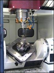
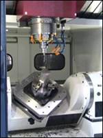
Enter the humble machine tool probe. Most of you have seen them and many may have used them for setting a WPC (workpiece coordinate) or maybe some basic gaging. But how many have looked at the probe as a device that can literally be used as a Virtual Operator to perform many of the everyday, time-robbing process that eat into profitability.
Examples of probe use for moldmaking include:
1. Setup
- Accurately establish WPC for mold base and core/cavity work.
- Position electrodes on center of pallet tooling to reduce/eliminate re-centering of electrode on the EDM.
- Check for loading errors on pallet system.
- Calculate part rotation for three- and five-axis machines.
- Calculate five-axis part orientation in combination with software like NCT+ from Numerical Control Software Solutions LLC.
2. In-process gaging
- Check rough stock condition before finishing tools go to work.
- Check part orientation and reset after roughing.
- Adjust for thermal variation between rough and finish.
- Automatically adjust tool compensation, H and D values.
- Determine exact stock for finishing.
3. Inspection and reporting
- Inspect finished parts before they are removed from the machine to avoid second setup.
- Check electrodes to verify correct overburn.
- Make sure all electrodes are in a negative stock condition.
- Reduce/remove need to “Second Check” electrodes at EDM.
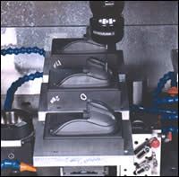
- Provide complete inspection reports for finished base, electrodes and core/cavity sets.
- Minimize downtime for secondary inspection processes.
- Reduce or eliminate bottleneck at CMM.
- Reduce or eliminate errors from manual inspection process.
- Eliminate subjectivity in reporting.
- Provide traceability of all machined components, per machine, shift, and operator.
4. Health check of machine
- Run pre-programmed health check on artifact to track machine wear.
- Health check as a precursor to ballbar and/or recalibration of machine.
- Quick check after a crash.
- Identify lead screw wear (pitch error), back lash and servo gain problems.
- Use for comparison date between annual/semi annual machine calibrations.
5. Virtual Operator
- Control manufacturing process for light attended or full unattended operations.
- Track and adjust for thermal changes in the process.
- Make “the ghost-in-the-machine” take a vacation.
Types of Probes
Currently there are two basic types of probes on the market, regardless of manufacture: touch trigger and strain gage. The touch trigger probe is the most common and provides very good functionality in the 21/2 measurement arena—flat surface hits for X,Y or Z, standard Bore or Boss measurements and updating of work and tool offsets.
However, in a moldmaking application the need for a probe capable of measuring from any vector in three axis (in some cases five axis) is critical and provides the most useful information. While any touch trigger probe can be used (with the appropriate software) to check a feature in three axis vector approach, the result can be anywhere from .0005 to several thousandths off.
The user has two solutions for this. With a spherical artifact, the user can program all of the vectors the inspection program will use onto the sphere, run the program and create calibration data for each vector and apply that data to the final inspection report. A time-consuming process requiring considerable hand editing and/or special software. The most effective method is to use a strain gage probe.
Proper Probe Calibration
We have already talked about the need for machine calibration using a laser or ball bar type method. Calibrating the probe to the individual machine is a very critical step and one that must be done precisely if the accuracy required for moldmaking is to be achieved.
Keep the following four points in mind as you prepare to calibrate and use a machine tool probe.
- Your CNC machine can be just as accurate and repeatable as your CMM—just treat them the same.
- Calibration on the CMM or machine tool probe is only as good as the setup.
- If you’ve had your CNC laser calibrated, be sure you incorporate the corrected pitch error and backlash comp values.
- Don’t expect to get .0001 accuracy from your CNC if your shop temperature varies 30 degrees.
These are the basic steps, which apply to calibrating any probe, regardless of manufacture.
- Select a traceable artifact. Usually a ring gage and/or sphere is best.
- Determine the EXACT diameter of the gage (yes, that means +/-.00001).
- Locate the gage on the machine table or Z plane surface in the machine. Avoid using the extreme corners of the machine. Instead, place the gage in the most used area of the machining envelope. The gage should not be clamped, but rather “supported”. Three strong magnets nested about the profile works best. Be sure the gage is dialed in flat also.
- Using a .000050 test indicator, center the spindle over the ring gage and sweep in to exact center. The more accurately you perform this process, the more accurate your inspection results will be. Now, once it’s dialed in to center, set a WPC like G54 to this center. Note: With the G54 XY set, move the spindle off center about .500 inches. Perform an MDI command as follows: G1 G90 G54 X0 Y0 F25.0 and execute the command. It’s very important that you use a feed move, not a rapid move in this line. The machine will now feed to center of the gage.
- Sweep the gage again and make any adjustments necessary. Repeat this process until the test indication runs with less than .0001 TIR.
- For calibrating the Z length of the probe, set a rough length with a scale. Use the top of the gage or another flat, smooth surface with a known location from the center of the gage. Using your most precise method, set the G54 Z0 value to this surface.
- Load your calibration program immediately and edit the appropriate coordinate position, tool number and the exact diameter of the gage. Run the calibration program.
- With calibration finished, view the calibrated radius, x and y offsets for the probe. Note: This value will always be slightly smaller than the physical radius of the stylus. This is normal. You also will notice several tenths of variation from center. This also is normal.
- Calibration is now complete. While calibration does not need to be done each time the probe is used, it should be done routinely—every few months if the probe is left in the tool magazine, and every two weeks if the probe is hand loaded, or anytime there a discrepancy from a second inspection source or health check. A simple calibration fixture can be made that reduces the process to about 20 minutes or they can be purchased from companies.
Proper Calibration Equals Reduced Setup, Inspection Costs and Wasted Time
With your probe now properly calibrated, you’ll never have another scrap part. Not entirely true, but you do have a machine/probe combination that will significantly reduce your setup, inspection costs and wasted time on a surface plate along with providing the gateway toward Virtual Operator. These benefits are not only accurate; they are within the capabilities of almost any shop.
Related Content
MMT Chats: The Connection Between Additive Manufacturing Education and ROI
This MMT Chat continues the conversation with Action Mold and Machining, as two members of the Additive Manufacturing team dig a little deeper into AM education, AM’s return on investment and the facility and equipment requirements to implement AM properly.
Read MoreHands-on Workshop Teaches Mold Maintenance Process
Intensive workshop teaches the process of mold maintenance to help put an end to the firefighting culture of many toolrooms.
Read MoreLeading Mold Manufacturers Share Best Practices for Improving Efficiency
Precise Tooling Solutions, X-Cell Tool and Mold, M&M Tool and Mold, Ameritech Die & Mold, and Cavalier Tool & Manufacturing, sit down for a fast-paced Q&A focused on strategies for improving efficiencies across their operations.
Read MoreMMT Chats: 5 in 5 with Best Tool and Engineering
MoldMaking Technology Editorial Director Christina Fuges reveals 5 best practices for improving efficiencies within shops...in 5 minutes. Our guest is Joe Cherluck, President of Best Tool and Engineering in Clinton Township, Michigan.
Read MoreRead Next
White-Light Scanning Validates Faster, Better Processes for Molded Auto Interior Trim at Eifel Inc.
The use of white-light scanning and photogrammetry ensures accuracy of tool building programs.
Read More3-D, Non-Contact Scanning for Inspection: Info for Moldmakers
Understanding the differences and similarities between CMM and 3-D scanning allows moldmakers to adapt to, apply and leverage 3-D scanning technology within their shop environment.
Read MoreNew Technology Helps Users Accurately Design Molds
VISI-Flow software helps mold shop determine optimum mold specifications.
Read More


.jpg;maxWidth=300;quality=90)


