Maximize Hard Milling with Balanced Machining Process Factors
Successful application of high-speed milling of hardened steels requires an understanding of the many factors that influence the entire machining process.
To maximize productivity and reliability, mold shops often machine a large portion of their products from hardened steels. Historically, hardened steels have been rough milled at low feeds and speeds, with large depths of cut and stepovers. The process is agonizingly slow and can produce deep stair-steps on the part, which necessitate multiple semi-finishing and finishing operations. Alternatively, shops will rough mill a soft block, have it heat-treated, and then bring it back to the milling machines for a number of setups for semi-finishing and finishing. Another approach to hardened steel machining has been EDM, a process that is also very time-consuming.
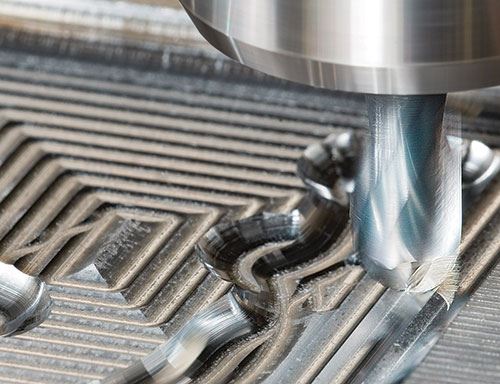
These lengthy processes are increasingly being replaced by high-speed hard milling, which involves taking light depths of cut and using high feed rates. This process enables shops to drill holes and water lines in a block, perform heat treatment, and then apply the high-speed strategies to rough and finish in one setup. Metal removal rates are high, and semi-finish and finish operations are minimized, because the hard-milling process results in near-net-shape parts. Surface finishes in the range of 10-12 rms are possible. The result is increased productivity, and decreases in the costs of setup and repetitive part handling.
Influencing Factors
Successful application of high-speed hard milling, however, requires an understanding of the many factors that influence the process:
Hardness and Machinability
The measured hardness of typical hardened steels is in the range of 48-65 HRC. However, when it comes to real-world machinability, the Rockwell number does not represent the whole story. For example, D2 tool steel hardens to about 60-62 HRC, but it machines more like 62-65 HRC due to a chromium content of 11-13 percent that increases toughness. For D2 and similar multi-constituent alloys, it is necessary to apply machining parameters from the tooling supplier that are intended for harder materials.
Constant Chip Load is Crucial
A key to tool life and part quality in milling, and especially in high-speed milling of hardened steels, is maintaining constant chip load on the milling tool’s cutting edges. Chip load equals the feed rate divided by the spindle speed multiplied by the number of cutting flutes, and chip load that varies widely or is too low or too high will cause tools to wear out too fast, chip or break.
Maintaining constant chip load is a particular problem when machining the 3D contours that are characteristic of moldmaking. Programming a straight high-speed, high-feed tool path generally is routine, but in milling complex shapes, the load on the tool changes and the machine may not be able to maintain the desired chip load. For example, when a cutter arrives at a 90-degree corner, the tool’s engagement angle doubles and cutting forces increase. If the feed rate is not reduced, the tool will wear rapidly or break. Machinists can manually reduce feed via feed-override controls, or the CAM program and machine tool control can combine to back the feed rate down in order to machine varying mold contours.
A machinist can confirm if the specified feed rate is being achieved by loading the CAM program and tools into the machine and setting the tool’s Z height about 1 inch above the part. A dry run will reveal the actual feed rates. Basic physics dictates that maintaining the desired feed rate and chip load 100 percent of the time is not possible. A good rule of thumb is: If the programmed feed rate is not maintained for 80 percent of the cycle time, then spindle speed must be reduced accordingly to maintain consistent chip load.
For example, in an application where a feed rate of 100 inches per minute at 30,000 rpm will produce the desired chip load, the correct feed may be achieved for some portion of the operation but may fall to 40 inches per minute for other parts of the process, producing an average feed of 50 inches per minute. In this case, cutting the speed in half will most likely produce the desired chip load. Lowering the spindle speed will nominally increase cycle time, but tool life will increase in turn. Milling calculators are available to provide the parameters needed to achieve constant chip load.
Minimize Tool Runout
Another critical but often overlooked factor in milling operations is tool runout. In general, runout greater than about 0.0004 inch (one-seventh the diameter of a human hair) can cut tool life in half. Minimizing runout grows in importance when employing very small tools. For some small tools, 0.0004-inch runout will double the chip load on a single tooth, causing accelerated wear on the tool’s cutting edge. Using expensive machine tools and expensive cutting tools but employing bargain toolholders is a recipe for problems. High-precision holders, including shrink-fit and hydraulic, among others, will essentially eliminate runout as a negative factor.
Avoid Excessive Finishing Stock
Many shops make the mistake of leaving excess part stock for finish milling. For cutters of about 1/8-inch diameter and larger, leaving about 1 percent of the cutter diameter for finishing is recommended. For example, when applying a ½-inch-diameter tool, stock for finishing should be about 0.005-inch, or for a 1/8-inch-diameter cutter, finishing stock should be 0.002-0.003 inch.
For smaller tools, determining a sufficient amount of stock for finishing may be a case of “feel,” or trial and error. One percent of a 0.020-inch-diameter ballnose cutter’s diameter is 0.0002 inch, but the amount of stock may be insufficient and the tool may rub the workpiece material instead of shearing it, thus hastening tool failure. For the 0.020-inch-diameter cutter, finishing stock of 0.001 inch or 0.0008 inch would probably be more appropriate.
With small tools in particular, excessively large steps between finishing tools will cause problems. Starting with a 2-mm tool (1-mm radius) to create a 0.2-mm radius in a corner, some machinists will next apply a tool with a 0.4-mm radius. Under those circumstances, the chance that the tool will break is high. A better progression might be to next use a 0.8-mm-radius tool, then a 0.6-mm, and finally tools with 0.4-mm and 0.2-mm radii. This conservative method will consume a few more tools, but tool life will be greater for the tools that are applied, and the risk of breakage is small.
Utilize Premium Programming
Programming software is critical in maintaining chip load. Top-of-the-line CAM systems employ a larger number of individual points to define a tool path than less-capable programming systems. The CAM program also manages tool entry and exit to moderate forces on the cutting edge. Although more capable CAM software is usually also more expensive, the benefits generally outweigh the initial higher cost.
Machine controller capabilities play a role in efficient milling as well. To efficiently carry out high-speed milling strategies, a machine must have the computing power to look ahead and smoothly handle the rapid changes in machining parameters dictated by the CAM program. Older controllers and servos can’t necessarily process as many blocks per second as are needed to follow the complex machine movement commands of high-speed milling.
Manage Cutter Life
Close consideration of chip load, runout and other issues such as machine rigidity can produce surprising results regarding tool life in high-speed milling. Properly applied tools can last hours when milling hardened steels. Of course, the definition of tool life is a factor as well; the demands of the customer receiving the mold regarding surface finish may limit the amount of time that a tool can be run before being changed.
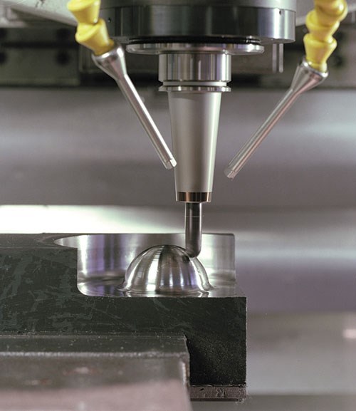
Extreme heat negatively impacts tool life, so the light depths of cut used in high-speed milling can boost tool life by maximizing the amount of time the cutting edges have to cool while outside the cut. To avoid thermal shock, air blast or oil/air mist generally replaces coolant when materials harder than 48 HRC are being milled. Although in some cases liquid coolant flow can clear chips and prevent recutting, an air blast is a better choice because it does not subject the tool to rapid, large changes in temperature.
Use the Right Tool
The industry-wide trend toward tighter tolerances includes moldmaking products, and those demands are reflected in the tools used to machine the molds and their components. A few years ago, a typical radial tolerance for a ball mill was 10 microns; now it is closer to 5 microns. A ballnose end mill that is not true to form will produce parts that do not match. Avoiding that kind of error is critical in moldmaking where, for example, liquid silicone rubber can form flash in mold mismatch gaps as small as 2 microns.
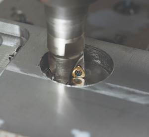
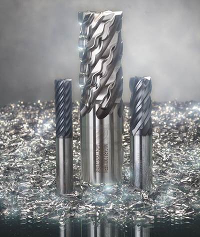
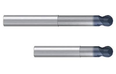
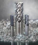
Because milling hard materials generates a significant amount of heat, many of the carbide end mills used in hard milling feature thermal-barrier coatings such as aluminum titanium nitride (AlTiN). These tools generally have hard micrograin carbide substrates (8 percent cobalt content) for heat resistance and strength, and negative cutting edge rake geometries to resist chipping. Cubic boron nitride (CBN) tools can be used in finishing operations, and inserted end mills are effective in roughing.
Very small milling tools can create features that formerly were only achievable with EDM. Tools as small as 0.1 mm (0.0039 inch) in diameter are available, and even such tiny tools can be effectively applied at high speeds with short flute lengths.
Balance All Factors
Precision tools, sophisticated CAM software, high-capability machine tools, premium toolholders and details such as coolant alternatives should be applied together to maximize the productivity and quality of hardened steel milling. Tooling, machine tool and workpiece material suppliers typically are more than willing to provide their expertise to help shops achieve a true process balance and meet their productivity goals.
Related Content
Maintaining a Wire EDM Machine
To achieve the ultimate capability and level of productivity from your wire EDM on a consistent, repeatable and reliable basis, regular maintenance is a required task.
Read More6 Ways to Optimize High-Feed Milling
High-feed milling can significantly outweigh potential reliability challenges. Consider these six strategies in order to make high-feed milling successful for your business.
Read MoreThe Benefits of Hand Scraping
Accuracy and flatness are two benefits of hand scraping that help improve machine loop stiffness, workpiece surface finish and component geometry.
Read MoreRevisiting Some Hot Runner Fundamentals
What exactly does a hot runner do? If you’ve been in the injection molding industry for any length of time, you might think the answer is obvious, but it is not.
Read MoreRead Next
How to Hard-Mill Effectively
These are five rules for improving cutter performance and cutter life while maintaining tight tolerances during hard milling.
Read MoreUnconventional Strategies for Roughing
Arc of contact and average chip thickness are essential for optimizing rough-machining operations.
Read MoreTips for Successful Hard Milling of Complex Molds
And when mold and die applications demand hard milling of materials up to 66 HRC, using the right end mills, cutting parameters and machining methods is critical for success.
Read More



.png;maxWidth=300;quality=90)

