Heater Selection and Tips to Successful Heater Installation
Design of a mold should ideally include the heater in order to locate the heat where it is really needed. Access to heaters, thermocouples and connectors is crucial to a good mold design.
Heater Selection
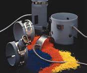
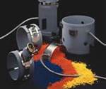
Selecting the right heater for a molding application is critical to the success of any operation. The most common heating elements specified for use in molds are cartridge, tubular and strip heaters.
In order to select the right heater for an application, heat requirements as well as physical requirements need to be considered. Heat requirements include knowing the temperature that needs to be reached and how quickly, along with an awareness of potential heat loss due to conduction, radiation and convection. Physical requirements include evaluating the physical space in which the heater needs to fit and any insulation, lead terminations and junction boxes that require additional space.
Heater Installation
Once the heater is selected, the following factors must be considered: temperature control, lead terminations, condensation, insulation, ground connections and accessibility. Each of these factors needs to be addressed prior to installation.
Temperature Control/Thermocouples
Proper temperature control will ensure consistent part production. The selection of a temperature controller is simply based on features and characteristics that are essential. The majority of current designed controls have a full range of diagnostic functions to check processing conditions. The most important are the location of thermocouples, evaluation of control zones and optimization of amperage (normally 15 or 30 amps).
Basic control of the mold temperature may be as simple as inserting a thermocouple into the mold and attaching it to an exposed surface. Certain types of heaters have built-in thermocouples. Cartridge heaters with internally positioned thermocouples are located in several possible positions along the heater's length. The most common positions and types of cartridge heater thermocouples are bottom grounded at the end disc opposite the leads; positioned at a point along the heater length and grounded to the sheath; or positioned in the center of the heater for relative temperature sensing.
In the U.S. plastic molding industry, type "J" iron/constantan thermocouples are the most commonly specified. There are basic procedures to follow when checking the integrity of the thermocouple. Start by inspecting the connections at the control, checking the continuity of the T/C to see its condition and watching for pinching that may cause a secondary or false junction. These inspection procedures apply to thermocouples externally applied to a mold as well as those that are internally positioned.
When a thermocouple fails, production time may be lost while replacing the heater. A solution is to use removable mineral-insulated thermocouples, which are available in a bottom grounded design - thus eliminating the need to remove the heater for replacement. This style of removable thermocouple also is available in some runnerless bushings, probes and torpedoes.
Lead Wire Channels
When a current is circulating through the lead wires, it tends to generate heat and magnetic fields. It is not a good idea to press these wires together, so if possible always oversize wire channels by 50 percent. It also is recommended to split wires into different channels and cover the external wire channels to prevent damage. Bends in lead exits should never be forced and enough length should be left to comfortably make junction box connections. Corners should be rounded to avoid the peeling of insulation during assembly. Finally, all wires should be tagged to avoid confusion in the junction box connections.
Condensation
Heaters used in molding applications are susceptible to condensation, as the heater is generally hot and the mold is generally cold. This is a combination that produces unavoidable condensation. To minimize damage, properly designing the draining channels from the leads to the bottom of the mold is essential. The wire channel should always move away from the heater at a 45-degree angle to keep condensation water from reaching the heater connections. Cartridge heaters can be sealed against moisture by potting with RTV or epoxy, or by wiping the terminal area with a silicone varnish.
Another common moisture problem occurs when heaters are taken out of storage and placed directly into mold operation. Not only can this cause excessive electrical leakage, but also may result in a grounded condition. Unless the heating elements were constructed to be sealed against moisture, they will most likely have absorbed moisture from a previous cool down process. Following some basic start-up procedures on the molding floor will help to slowly drive any moisture out of the heater. Some temperature controls on the market monitor the leakage current to ground. When this current exceeds an acceptable standard level, the power output is reduced - slowly baking out the system until the safe level is reached. Then full power is applied to the heater. This type of function is often called "soft start."
Insulation
Design of a mold should ideally include the heater in order to locate the heat where it is really needed. Insulating supports and blocks can be designed so that the heat is located in specific mold spots, keeping heat loss to a minimum. Ceramics, titanium and other special materials such as polymides can be used, generally providing good performance at a reasonable cost. Insulating materials may be purchased standard or machined to final dimensions to fit all applications. Proper placement of water channels close to the insulation will allow for better control of the remaining heat.
Termination Boxes
Today's market offers numerous options for termination (junction) boxes that may be used in various applications. Clear indications for connections, power separate from T/C, terminals clearly numerated and a good male/female fit are characteristics that should be included in a junction box. The best location for the box is on top of the mold, avoiding water contact or hydraulic spills. It also is a good idea to locate the junction box separate from the mold by at least one inch - protecting it from vibrations and shocks.
Ground Connections
Electricity always finds the shortest path to ground. If other grounding is not present, that path will always be the T/C, which can produce failure and will eventually burn out the thermocouple. A T/C is designed to handle .008 volts, while a standard power leakage can be as high as 50 to 80 volts - depending on the initial moisture present in the heater. Improper ground connections are a major cause of mold downtime, therefore it is important to make sure that the termination box is "grounded" to the mold.
Accessibility
Access to heaters, thermocouples and connectors is crucial to a good mold design. Keeping downtime to a minimum depends on easy access for maintenance. Whenever possible, a knockout hole should be incorporated into the mold design to allow the heater to be pulled out with fewer complications. When it is necessary to remove a heater for maintenance purposes, extraction also can be complicated by oxidation and contamination as well as by heater length. To facilitate removal under difficult circumstances, flanges, threaded bushings, a pull strap or other appendage styles should be considered. A last resort for removing a seized cartridge heater is to drill it out - leaving the hole enlarged, rough and uneven. In this case, the hole diameter should be increased to the next heater diameter.
Making the time to concentrate on proper heater selection and installation will help provide a mold operation with cost savings, minimal downtime and consistent part production.
Related Content
How to Eliminate Chatter
Here are techniques commonly used to combat chatter and guidelines to establish a foundation for optimizing the moldmaking process.
Read MoreThe Ins and Outs of Hot Runner Temperature Control
A training checklist that explains the why and how of proper hot runner temperature control and system management.
Read MoreHands-on Workshop Teaches Mold Maintenance Process
Intensive workshop teaches the process of mold maintenance to help put an end to the firefighting culture of many toolrooms.
Read MoreSolving Mold Alignment Problems with the Right Alignment Lock
Correct alignment lock selection can reduce maintenance costs and molding downtime, as well as increase part quality over the mold’s entire life.
Read MoreRead Next
How to Select the Correct Heater Insulation Material
Understanding why insulation is a key to heater life and performance.
Read MoreReasons to Use Fiber Lasers for Mold Cleaning
Fiber lasers offer a simplicity, speed, control and portability, minimizing mold cleaning risks.
Read MoreAre You a Moldmaker Considering 3D Printing? Consider the 3D Printing Workshop at NPE2024
Presentations will cover 3D printing for mold tooling, material innovation, product development, bridge production and full-scale, high-volume additive manufacturing.
Read More


.jpg;maxWidth=300;quality=90)


