Designing Molded Products Just Got Simpler
Rules-based design software increases manufacturability and reduces design time
The world of collaborative product development is far from ideal, but the tools in it are getting better every year. Digital design software now affords unique opportunities to moldmakers who want to provide early input on the molded features of designs. The software offers capabilities that, used strategically, can shorten design cycles while improving part manufacturability. The latest modeling tools provide new customizing methods for embodying a moldmaker's knowledge and shop capabilities in initial and successive generations of product designs.
In order to understand how best to take advantage of digital modeling software, let's take a look at its evolution and the challenges it has presented to designers and moldmakers.
Beyond Designing Geometry: Context
The earliest computer-aided design (CAD) tools were what are called explicit. Each aspect of a design was a separate geometric entity, created painstakingly one at a time by drafters. I say drafters because explicit CAD software was principally a tool for generating drawings, not revising designs.
About twenty years ago, parametric modeling software emerged and revolutionized product development. The new tools enabled designers to define a specific, history-based relationship between the geometric features in the model, such that a revision in one element would automatically bring about a corresponding change in another. The software was a huge breakthrough, and it changed the way that design teams could define products. By the 1990s, parametric CAD tools had swept the market because they promoted sophisticated design definition along with greater ease of revision.
Parametric tools also included a library of predefined common geometric features that designers could quickly use and customize without employing the detailed drafting steps of previous design software. At this point, all manner of suppliers, including moldmakers, realized that they could add their input to a design as it was being made, ensuring that a product design was more manufacturable from the get-go.
This new speed of design allowed for greater design review and optimization. It also encouraged team participation, including experts from manufacturing and tooling. However, as with all design tools, parametric design software has its limitations. Because its geometric features are history-based, created step-by-step in a certain order, some design changes are not as easy to make as others. Altering one aspect of the geometry may cause a feature to change in unexpected ways, forcing a time-consuming redesign.
For example, there is a company that produces a flat display screen for computers and televisions. An important piece of intellectual property on this product is the design for a network of ribs that contribute rigidity to the lightweight plastic frame around the screen. The completed rib model reflects sophisticated input about molded parts. Each rib has a certain thickness, determined by flow-through and cooling rates, and it has a little draft for easy removal from the mold. It has fillets and rounds for strength. A great deal of geometry, and a great deal of design time, went into defining this rib. And once it's designed, say, for the upper right-hand corner of the screen frame, it ought to be a reusable feature for the other corners.,
But it isn't. The design context - the extrusions and assemblies around a given rib - change the structural demands on it. The rib in the lower left corner bears the weight of heavier components - more than the original rib in the upper right corner. As a result, the lower left rib will need to be thicker and a little shorter. The change in the thickness likewise changes the size of the fillets and rounds. But here's the problem: in the parametric modeling tools, the first rib is defined as many individual bits of geometry, each bit defined in relation to others. To create a second rib with differing geometry, the designer - and the moldmaker - might as well start again from scratch.
It could have been worse. What if, after the screen design is nearly finished, new requirements compelled the engineer to add a curved boss to the outside of the display screen? The frame thickness remains constant, but now the inside of the frame is curved, right where the rib crosses. If you do this with parametric tools, the bottom of the rib won't touch the frame any more at that point, creating an undercut that will weaken the final design, complicate the moldmaker's work, and potentially slow production times. If the designer reworks the rib to meet the curved surface of the indentation, the height of that section of rib may cause mold-filling difficulties.
The designer has other means of catching manufacturability problems, of course. There are a number of software applications, both in suites and in stand-alone products, that assess the manufacturability of molded parts based on CAD models. Unfortunately, these tools are primarily for use after the fact, once the model geometry is complete. Making additional changes at this stage can be time-consuming, even difficult, depending on the relationship between the feature being changed and the part geometry linked to it. If you think this article is spending too much time talking about geometry and not enough about molding, you're absolutely right. Lately, the creators of new modeling software agree with you.
Playing by the Rules: Functional Modeling
Geometry is really a by-product of design, not the basis for it. The essence of a part feature, such as a rib, is its function. Function is not expressed by dimensions, but by the rules that govern the behavior of the feature, no matter what its context on the part. In a nutshell, that is the philosophy behind rules-based design software tools that offer functional modeling capabilities. The software automatically generates complex geometry and establishes associative relationships between part features.
In the display screen example above, revising a rib design was complicated because the designer worked in parametric CAD software. In that medium, he could not define a rib by the characteristics that help a rib to strengthen a part. All he could do was build geometry. By contrast, rules-based design software enables design teams to define a rib so it behaves intelligently according to its important qualities, such as:
- A rib extends across the inside (core-molded side) of a molded part, but never extends to the outside of the part.
- The bottom of a rib continuously touches the inside of a molded surface.
- The ends of a rib touch another feature - the part wall or another rib - along their entire height from top to bottom.
Defining a rib this way enables the designer to re-use a rib easily. Where the inside of a part is shallower, the new rib does not extend outside the part to the wall. Where the inside of the molded part is irregular, the rib bottom automatically stretches down to eliminate gaps. If the rib is copied into a wider section of the part, its ends extend until they touch another feature and fulfill their function.
The new rules-based modeling tools offer the designer and moldmaker digital libraries of function-based features: ribs, pockets, rounds, fillets and so forth. If your product uses a particular pocket over and over, you can design it once; define the draft, rounds and fillets; and save it to copy into new designs. Libraries of these rules-based, user-defined objects (UDOs) capture manufacturing expertise so that an engineer creating a brand-new product already knows that it is manufacturable.
UDO libraries pay off even more on second- or third-generation designs. For instance, a company that designs cell phones is under constant pressure to produce phones in a wide range of flashy shapes. Every six months, the company releases a new generation of phones with new bodies. But the phone components - the chip, the antenna, the microphone, the speaker and the display screen - remain fairly constant from one phone style and one generation to the next. The molded features that snap them in place, hold them, protect them or guide them are fairly consistent as well.
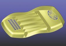
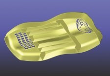
Because the shape of the phone body changes with each style and each product generation, the molded features must change so that they can fulfill their functions. If you have only created the geometry of these features, you have a long redesign ahead of you, often under deadline pressure. But if you have created a user-defined object for each feature, capturing its function and behavior with rules-based software, the design will adapt itself to any new body shape the marketing department desires. The chip frame will extend to the floor of the new body, still holding the chip rigid. The microphone and speaker grilles will retain their parallel open slots, no matter how altered the surface topology of the phone (See Figures 1 and 2).
Making Your Own Rules: Application Development and Function Design
Some rules-based design tools will even enable you to define and customize new functions. Going back to the cell phone, suppose you had collaborated on designing a special snap-fit connection to open and close the battery compartment. Snaps are common molded parts, but let's say this snap-fit is a unique design, one you intend to patent and license. If you could add it to a CAD feature library, just think of the design time you would save.
In the latest rules-based modeling software, you can use an application development framework to define the behavior of the snap-fit - to write your own rules, as it were. The cantilever beam and catch of the snap-fit have interlocking, angled lips whose height is defined in relation to each other. The angle and direction of each lip are constrained to reduce the complexity of the mold. The snap-fit cantilever is thin enough to bend during insertion and thick enough to withstand strain for the life of the product. And there is a defined relationship between the deflection of the cantilever and the height of the lip. By creating these functions in the software and using them to define the snap-fit, you will be able to reuse that feature with confidence that no matter where you put it, it will fulfill its purpose and still be readily manufacturable.
Digital modeling has come a long way. Now that design software can model the function as well as the shape of product features, a world of possibilities opens up to capture the unique behavior and characteristics of molded products. That can only speed up product development and improve manufacturability. It still won't be an ideal world, but working in a slightly better one can't hurt.
Related Content
What Is Scientific Maintenance? Part 1
Part one of this three-part series explains how to create a scientific maintenance plan based on a toolroom’s current data collection and usage.
Read MoreHow to Select a Mold Temperature Controller
White paper shares how cooling channel analysis, which collects maximum pressure drop, total flow rate and heat dissipation, eases the performance evaluation of mold temperature controllers.
Read MoreTips for Tackling Mold Design, Machining, Cutting Tool and Wear Challenges
Tips for tasks ranging from reducing risk in part design and taking advantage of five-axis machining to refining cutting tool performance and reducing wear with guiding and centering systems.
Read MoreHow to Analyze and Optimize Cutting Conditions to Reduce Cycle Time
Plastic injection mold design and manufacturing company puts NC program optimization software module to the test. The results were surprising.
Read MoreRead Next
Reasons to Use Fiber Lasers for Mold Cleaning
Fiber lasers offer a simplicity, speed, control and portability, minimizing mold cleaning risks.
Read MoreHow to Use Continuing Education to Remain Competitive in Moldmaking
Continued training helps moldmakers make tooling decisions and properly use the latest cutting tool to efficiently machine high-quality molds.
Read MoreAre You a Moldmaker Considering 3D Printing? Consider the 3D Printing Workshop at NPE2024
Presentations will cover 3D printing for mold tooling, material innovation, product development, bridge production and full-scale, high-volume additive manufacturing.
Read More


