Data Analysis Links Design With Manufacturability
New advancements in coordinate measuring machines give moldmakers a new tool in improving operations.
Share
Read Next
The ability to control the machining process so that mold dimensions consistently match those of the model or print is the single most effective way to improve quality and throughput in moldmaking operations.
To do that requires the ability to determine the dimensional accuracy of molds and the parts they produce. Until recently, that has been a difficult and time-consuming operation requiring the use of a variety of manual measuring instruments and custom engineered fixed gages. Advances in measurement and inspection software, however, have made the use of coordinate measuring machines (CMMs) a viable and efficient method of improving moldmaking operations.
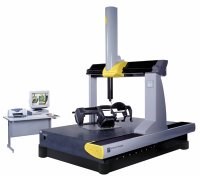
CMMs collect detailed dimensional data by moving a sensing device called a probe along workpiece surfaces. This dimensional information is compared with blueprint specifications. If dimensions begin to drift out of tolerance, modifications can be made to the machining process to correct the problem.
Scanning Speeds Data Acquisition
Unlike angular, prismatic parts that require only a minimum number of data points to establish a dimensional definition, precision measurement of contoured, free form shapes, such as plastic injection molds, requires the compilation of a large number of data points. Today there are CMMs available that can automatically measure the 3-D shape and form of workpieces at up to 1,000 points per second using current contact probe technology. Other CMMs can gather up to 20,000 points per second using advanced non-contact sensor technology. With the availability of inexpensive scanning CMMs and the capability to effectively harness the power of massive amounts of dimensional data through CAD/CAM systems, moldmakers can exercise a level of control over machining processes never before possible.
Open-loop and closed-loop scanning are the two techniques that these machines use to collect data. Open-loop scanning is a high-speed technique used with continuous analog probes on parts whose geometry is mathematically defined, allowing the machine to be programmed to maintain contact with the surface. The probe is driven along the known path of the nominal surface and records the magnitude of the error between the actual surface and the nominal. Verifying the dimensions of a mold after machining is a typical application of open-loop scanning techniques.
In a closed-loop system, the probe detects changes in surface direction of the part and adjusts itself to maintain contact with the part surface. Closed-loop scanning is slower than open-loop scanning, but very accurate. It is particularly useful for digitizing unknown complex shapes for reverse engineering applications. Data collected in this manner can be used in conjunction with a CAD system to create electronic part models for reverse engineering and construct and/or verify tooling paths for machining operations. Scanning also is a fast, efficient method of archiving dimensional data for later use. For example, a moldmaker may design tooling on a CAD system, machine it, test it to find that the molded part doesn't meet design specifications, then modify the mold to refine its shape. The dimensions of the modified mold can be digitized using a CMM, and the information archived in a CAD database for later use if the mold has to be repaired or replaced.
Software Makes the System Work
While hardware is important for accur-ate data gathering, software is the key to getting the most value from dimensional data. Advances in metrology software offer powerful data analysis capability in a package that is easy to use. This inspection and measurement soft-ware is designed with an intuitive graphic user interface and quick start routines that simplify its operation so that operators of any skill level can use it to perform advanced measurement routines. The operation of the software has become so simplified that even with complex shapes such as molds, an operator using a manual CMM needs only to touch the part with the CMM probe where the data is required and the measurement is automatically taken. With a direct computer control CMM, the operator simply clicks on the area of the CAD model of the mold that needs to be measured. The software determines the nominal location and normal vector, offsets the probe radius accordingly, automatically measures the mold, and presents the deviation from nominal.
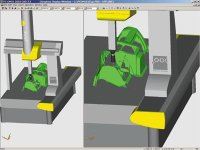
Part programming also can be performed offline in a virtual environment that does not require the availability of the CMM or the part. This is particularly valuable in those applications where the CMM is in constant use and operators don't wish to take it out of production to develop new part programs. The software's powerful 3-D animation tools allow users to simulate the entire programming environment, including the machine, probe and part. As the part program is created, simulated probe path and collision detection tools verify the program sequence. Everything that an operator would normally do to program a part on a CMM can be performed offline with the software.
Measured data can be organized in a variety of report formats that make analysis easier. Results of the data analysis can be used to adjust the machining process to improve the dimensional quality of the mold.
There are some special features that make this software particularly useful in moldmaking applications. For example, oftentimes a CAD model will be of the part geometry in a virtual state. Yet in the manufacturing process, there will be cooling that results in shrinkage of the resultant part. The software's shrink factor tool can shrink or expand the CAD data accordingly, so that accurate measurements are achieved. Contour analysis uses color contour maps to visualize the dimensional condition of the part and its deviation from nominal dimensions.
Advanced measurement and inspection software links seamlessly to CAD/CAM systems and provides interactive graphics for the generation of mathematical models and the verification of sculptured surfaces. It simplifies and accelerates reverse engineering applications by facilitating interaction between the CMM and the CAD/CAM system through standard and custom communications protocols. In the verification mode, theoretical and real points are compared in order to establish tolerance controls and statistical computations that are stored in a verification protocol. Any deviations are graphically displayed as vector lines originating from the selected points on the surface.
Coordinate measuring machines capable of scanning are an extremely flexible and cost-effective way for moldmakers to take advantage of the power of dimensional data to improve processes and the overall quality of moldmaking operations.
Related Content
Breaking Down 3D Scanning in Moldmaking
Identifying 3D scanning requirements and implementing the appropriate technology.
Read MoreProducts and Services for Multiple Moldmaking Needs
New year, new technology roundup! Featured here is a collection of product offerings, from profile milling cutters to industry-specific CAD/CAM software to innovative hot work tool steels.
Read MoreFour Micro Tooling Considerations
Issues involving gating, ejection, mold splits and direction of pull are of special concern when it comes to micro tooling.
Read MoreCT Scanning Helps Micro Molder Reduce Cost of First Article Inspections
CT scanning services performed by 3D ProScan, a division of NyproMold Inc. provides MTD Micro Molding with accurate, high-resolution internal and external measurements performed about seven times faster and at significant cost savings.
Read MoreRead Next
Dimensional Data Collection Through Coordinate Metrology: A Cost-Effective Way to Improve Moldmaking Operations
Advances in data gathering sensor technology and improved measurement and inspection software have made the use of coordinate measuring machines (CMMs) a viable and cost-effective method of improving moldmaking operations.
Read MoreHow to Use Continuing Education to Remain Competitive in Moldmaking
Continued training helps moldmakers make tooling decisions and properly use the latest cutting tool to efficiently machine high-quality molds.
Read MoreHow to Use Strategic Planning Tools, Data to Manage the Human Side of Business
Q&A with Marion Wells, MMT EAB member and founder of Human Asset Management.
Read More


.jpg;maxWidth=300;quality=90)


