Trends in NC Programming For Moldmakers
Twelve NC programming/CAM trends to help drive mold manufacturing.
To remain competitive in worldwide markets, moldmakers must use current or advanced technology whether it is in machine tools, operating software or NC programming software. This article addresses the current trends in NC programming or CAM software for moldmakers.
1. Process-Focused Software
NC programming software is evolving from use of basic instructions to covering a broader or complete process. A process-focused approach is better able to consider and supply the full needs of a specific type of user. Specific application solutions for moldmakers are now available that are focused on core and cavity design, mold base design, electrode design and machining, and/or machining of multi-cavity parts. Wizards can be used to create the processes. Each solution incorporates different machining strategies and parameters appropriate to the task. Moldmakers also can customize the software to enhance a process.
2. Capturing Best Practices
CAM software is now available to permit moldmakers to capture and re-use their best practices. Libraries of machining strategies tailored to best practices can be established from machining rules, templates, knowledge and feature-based machining. A set of machining rules can be defined by users based on the material, part geometry features and the operations to be performed, or templates can be captured and catalogued from actual usage. The strategies or processes can be stored and then applied to current and future machining tasks.
3. More Solid-Base Machining
Solids-based machining is now com-monplace in production machining and its usage is increasing in moldmaking. Machining is often accomplished directly on a solid model. The three main elements of solid-based machining system are: (1) a solid modeling system; (2) the ability to import the data contained within the model into the CAM system without translation; and, (3) a CAM system that uses the inherent intelligence and functionality with the solid model. Most software now supports machining on a tessellated solid or surface model, and solid and surface definitions can be intermixed with the same hybrid model.
4. Increased Use of Continuous Five-Axis Machining
This type of machining has long been employed in aerospace operations, but is now finding greater use in mold and die machining. Five-axis machines have had the reputation of being expensive and difficult to program. However, they are now more affordable at prices in the range of $100,000 to $200,000 and the price continues to decline. At this price, with software that is easier to learn and execute, and with significant benefits being achieved, continuous five-axis machining is gaining favor in moldmaking.
Performing some applications in continuous five-axis that have heretofore been done with three-axis NC machines can result in a number of advantages, including an elimination of manual positioning, fewer setups and tool changes, a reduction in in-process inventory, use of smaller and shorter tools, avoidance of EDM, which eliminates the need for electrodes, and greater manufacturing efficiencies.
Machine time is reduced and product quality is usually better because workpieces do not have to be moved from machine to machine for multiple operations. For complex shapes, users can machine five sides of a part without special fixturing, jigs or manually re-positioning. Dies, cores and deep cavities can often be more effectively machined in five-axis than in either three-axis or 3+2 cutting, since it results in continuous material removal.
5. Increased Use of 3 + 2 Machining
In addition to growth in continuous five-axis machining, five-axis positioning or 3 + 2 machining also is gaining greater acceptance by moldmakers. In this type of machining, a two-axis tilting rotary figure is added to a three-axis machining center so that parts can be positioned at different angles. Once positioned, the parts are then cut in three-axis. 3 +2 machining provides many of the benefits of continuous five-axis milling and for moldmakers it can serve as an alternative approach to either three-axis or five-axis continuous machining.
3+2 machining is particularly appropriate for cutting deep cavities or deep standing cores in molds. The user defines the maximum tilt angle, but does not need to define the specific tilt angles. The software finds the locations where tilt of the cutter is required and the minimum tilt angle to avoid hitting a side. The software will maintain that angle until a collision is apparent. At that point it will change the angle in order to avoid a collision. If an area is encountered that does not require a tilt, the software reverts the tool to a position normal to surface or one with less tilt. All repositioning of the tool can be done automatically with minimum amount of tilt. Software is sometimes employed to optimize the tilt angle of the tool. The toolpath from this process will look like continuous five-axis toolpaths.
6. Utilization of Production Machining Techniques in Moldmaking
To further automation, some mold-makers are incorporating production machining techniques into their operations. For example, “tombstone” machining has long been employed in production machining to increase productivity by producing multiple parts on multiple sides of a holding fixture with a single setup. This technique is now being employed in moldmaking so that multiple cores and/or cavities can be produced in a single setup or different machining setups for a given part can be placed on a “tombstone.”
Further, mill-turn machines—a staple in production machining—are being introduced into some mold shops, as there is a clear trend toward greater use of multi-function machine tools. The tools could be multi-axis and have multiple spindles, sub-spindles and turrets. The milling capability is comparable to that of some machining centers. Parts that previously required multiple turning and milling machines are now being produced on a single machine. These tools require advanced software to synchronize movement, provide visualization to the operation, and efficiently utilize the machines to minimize dead time. They may require new post processors to drive the tools. The savings in setup time, floor space and the increase in production efficiency can be significant.
7. High-Speed Cutting Is Becoming Commonplace
Most mold and die shops now employ high-speed machining. The software to support this technology must provide for fast and efficient transfer of data, smooth tool movement that minimizes any sudden change in direction, a constant chip load to maximize the life of the cutter and support of those machine tool features necessary to produce gouge-free, high surface finish parts. Surfaces must be tangent without gaps or overlaps.
Machining is sometimes done on the actual surfaces as opposed to tessellated surfaces to obtain a higher quality output. However, quality problems sometimes occur with high-speed machining, as the material can overheat, cracks can develop and the material can move. Nevertheless, the use of high-speed cutting has become mandatory for moldmakers and all CAM software vendors providing products to this industry segment must effectively support this technology.
8. Feedrate/Toolpath Optimization
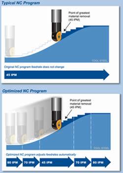
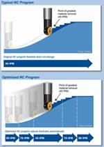
Typically, high-speed machining is accomplished with very small axial cut depths in order to achieve good surface finish and avoid damage to the cutter, workpiece or spindle. Feedrate optimization software can be employed to achieve better cutting efficiency with greater axial depths at the high feedrates of HSM, and protect the cutter, etc., in those few places where the chip load momentarily increases. Constant chip load toolpaths allow optimum use of the cutter’s strength and the machine’s speed and power. The software detects conditions where the chip load is too great, and adjusts the feedrate to a more reasonable level. It then returns the machine to a higher feedrate when chip load permits. Some CAM software vendors take the opposite approach of maintaining a constant feedrate, but optimizing the toolpath. This approach minimizes the machining problems associated with many changes in feedrate.
9. Further Automation and Greater Use of Knowledge-Based Machining (KBM)
The utilization of KBM is the centerpiece technology for implementation of semi-automatic and automatic toolpath generation. The two primary technologies for implementation of KBM machining are adaptive and/or generative. In addition, a KBM process can be either feature-based or parts-based. When employing feature-based machining, automatic feature recognition software can be used to examine a model, determine which features exist and extract the features for subsequent processing. Feature-based machining is becoming a common vehicle to implement KBM.
10. Feature-Based Machining (FBM)
In FBM, a part is viewed as a group of interrelated features such as pockets, holes, slots, etc. User-defined features also should be available, as users should be able to define their own sets of features along with specialized machining processes that improve the productivity in a shop. These features can be defined by design systems, manual identification or automatic feature recognition systems. Manufacturing fea-tures, as opposed to design features, are usually employed in FBM. Features define the faces of a part, the size and shape of pockets, slots, bosses and grooves; the location and types of holes, etc. A feature also describes how to produce the shape. Specific machining operations are applied to each feature. Features contain information and rules describing conditions, such as how and where material removal should occur, cutting depths, whether to use climb cutting or not, whether to spot drill or center drill, and preferred machining strategies for roughing and finishing.
FBM typically requires less programming time since one does not have to create or manage each machining operation. Features are easily revised by simply changing one or more individual parameters—such as depth or radius—and the entire part is updated. The programming process becomes more automatic. FBM has been most commonly applied to hole making and machining of prismatic parts in production machining, but it is now being applied to cutting of parts of complex shape in moldmaking.
11. Automatic Feature Recognition (AFR)
Feature recognition software is becoming more common in both production machining and moldmaking. It can be used to examine a model, determine which features exist, convert design features into manufacturing features, and extract the features for subsequent processing. AFR software automatically recognizes features on an imported solid, including faces, splines, holes, bosses, and closed and open pockets. All types of holes including through holes, threaded holes, counterbored holes, etc. can be detected and identified. If there is a design change, the revised model can be imported and AFR will associate the new model with the original features. When features are revised, changes are made only to the specific machining parameters that are different from the original solid.
12. Emergence of More Realistic Simulation
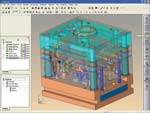
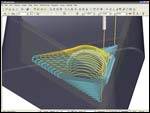
Significant improvement is being made in software for machine simulation, toolpath verification and rendering. Realistic simulation of the entire machining process including the machine tool, holders, machine components, cutting tools and stock can be made to provide the user with a complete picture of a machining operation. Simulation of the toolpath is provided to verify its accuracy. Collisions, gouges, undercuts, and any discrepancies between the target part and the machined part are shown. By comparing an in-process model with the designed part the rest material can be displayed. Rendering software provides for photo realistic images of the machined part. The verification and simulation software also is becoming more highly integrated with the toolpath generation software. Visualization of processes is becoming increasingly important for programmers, planners and machinists.
Competing in a global environment demands continuous improvements in processes, operations, methodology, technology, and a culture to meet and exceed expectations. Moldmakers must constantly look for ways to meet the faster, better, cheaper mantra of today’s economy, and being aware of the current trends in NC programming or CAM software for mold manufacture is one way to ensure your shop stays ahead of the competition.
Related Content
Precision Meets Innovation at IMTS 2024
After attending IMTS, it's clear that the integration of advanced technologies is ready to enhance precision, efficiency and automation in mold manufacturing processes. It’s a massive event, so here’s a glimpse of what the MMT team experienced firsthand.
Read MoreTolerancing in Mold Design, Part 2: Using GD&T to Address Conventional Tolerancing Issues
Mold designers can achieve a single interpretation of workpiece functionality when following the American Society of Mechanical Engineers Geometric Dimensioning and Tolerancing standard.
Read MoreMMT Chats: Solving Schedule and Capacity Challenges With ERP
For this MMT Chat, my guests hail from Omega Tool of Menomonee Falls, Wisconsin, who share their journey with using enterprise resource planning (ERP)—and their people—to solve their schedule and capacity load monitoring challenges.
Read MoreWhat Is Scientific Maintenance? Part 1
Part one of this three-part series explains how to create a scientific maintenance plan based on a toolroom’s current data collection and usage.
Read MoreRead Next
Conquering CAD/CAM Challenges
Leading software manufacturers and suppliers reveal how moldmakers can maximize efficiencies using the latest CAD/CAM equipment so they can program and cut complex molds in less time than ever before.
Read MoreSimulate and Optimize Your Mold Build Process
Mold shops can increase efficiency, lengthen tool and machine life and achieve better surface finish with the same software they use to verify their increasingly complex NC programs.
Read MoreHow CAD/CAM Is Making a Programmer’s Job Easier
Arming yourself with the appropriate information will help you select the right software to help your shop work smarter not harder.
Read More


.jpg;maxWidth=300;quality=90)

