CAM Reduces Cycle Time when Machining Mold Bases
Feature recognition, CAM capabilities and machine controller interaction can reduce cycle time when machining mold bases.
Hole drilling is one of the simplest operations in manufacturing, and simple operations often lend themselves to opportunities for optimization. This is especially true for the deep holes and cross holes required in mold bases to create necessary waterlines.
Waterlines in a mold are essential to controlling the temperature of the injected plastic, resulting in consistent heat and mass flow, controlled shrinkage, and high-quality parts. They act as heat exchangers when they are fed cool water, cooling the molded material.
Machinists and moldmakers for years have used manual programming techniques to prepare basic parts and simple geometries. These approaches may still be viable today for parts with a small number of holes, holes with standard sizes and holes limited to primary direction orientations.
For complex geometry, CAM procedures are frequently used to program the machine tools. In modern applications, these procedures are augmented by automation that can add intelligence to the geometry models and reuse proven technology processes. The automation can also include feature recognition that identifies geometry elements and technology macros to utilize standardized cutting templates for defined classes of geometry, such as holes. If CAM procedures are used with the right software, a complex job that includes hundreds of holes in multiple sizes, various orientations, and different threads and fit designations will be no more difficult to program than a simple fixture plate job with counter-sunk holes in the four corners.
CAM Considerations
Users should recognize that all CAM software will claim various capabilities, so further research is necessary to confirm if a vendor’s product can “do it” or do it well. “Doing it well” should include steps that save programming time and reduce machining cycle times, while simultaneously providing high efficiency and a low-risk workflow.
Feature recognition can reduce such programming time and help achieve a consistent workflow. This process scans a native or neutral formatted geometry file and organizes the data. The output defines the hole size as well as parameters such as through or blind, threads, surface quality, orientation, and steps/counter-sinks. The software’s ability to search the model and define and organize the geometry replaces manual user selections, which are time-consuming and prone to errors such as missed entities or not grouping similar geometry. These organized lists of geometry elements can then be matched to a database containing manufacturing data such as cutter sizes and cutting procedure sequences with depth of cut, spindle speed and coolant control.
Ideally, the cutting macro database will be locally developed technology based on cutter recommendations, machine tool capabilities and materials being cut. In fact, multiple macro databases can be appropriate to store information for large and small machine tools, or high-speed and high-power machines that may be found within the same end-user organization.
While pre-defined technology databases work in many environments, user-defined procedures also can be tailored to a specific environment, thereby enabling higher optimization. Keep in mind that the process to store best-practice cutting techniques into a database has to be compatible with a machine shop environment. This means having staff focused more on cutting chips than programming databases.
Compound Logic within the Macro Database
A powerful programming macro can contain compound logic. This means that one procedure can have if-then logic to meet the actual situation, for example, using a simple drilling or pecking process depending on hole depth.
If this logic is stored within one programming macro, the number of entries in the database is reduced, thereby simplifying user selections. This efficiency is evident when a newly hired programmer/machinist can use the shop’s existing database and simply select a ¼-inch hole process without debating when to select a shallow or deep process.
Using Smart Geometry
By coordinating manufacturing objectives within the design process, designers can make easy adaptations and improve the overall end product, for example, defining and adhering to a standardized hole chart with predefined colors, CAD layers or labels.
Additional automation can streamline programming further. Traditional feature recognition that involves searching the part model can be replaced with a simple match of attributes such as “blue” holes in the smart geometry with the macro database.
Deep Hole Applications
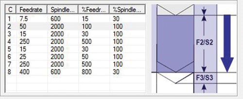
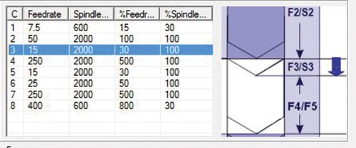
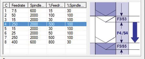
Deep holes present additional machining challenges such as coolant delivery and chip evacuation with a very long drill length. In addition, there oftentimes will be a crossing hole midway through the hole in a cooling network. This forces the drill to proceed from metal to air and back to metal, and to address associated process requirements for breakthrough and re-entry. Ignoring the changing terrain can lead to poor cutting conditions and increase the chance of breaking a drill deep inside the workpiece. To address this condition, additional information is needed from the part model.
It is important for CAM software to have extended feature recognition and solid modeling capabilities that can detect actual cutting conditions (see Figures 1a, 1b, 1c). To optimally manage these situations, the software should allow for different cutting conditions, such as feed rate, spindle speed and coolant control. However, if cross holes are not recognized at all or only recognized manually, the benefits of computer-based design and machining processes are greatly diminished.
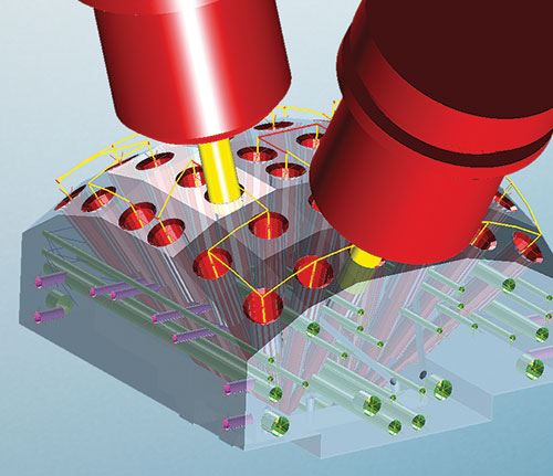
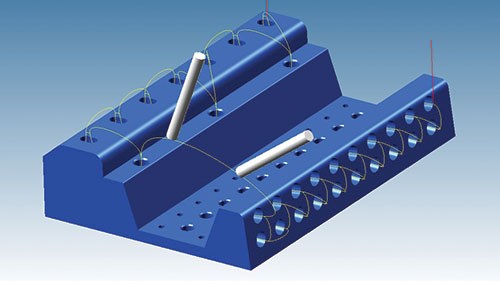
Multi-axis drilling, which is common in machining aerospace components, is also used in mold-base applications, including on the various faces of a simple block. Multi-axis drilling can save non-cutting cycle time between holes by using smart connections from hole to hole, no matter the orientation. Simple techniques can only group holes on one orientation. They also might go to a distant safe position on the machine between groupings, thereby increasing machining time. Using a multi-axis viewpoint, feature recognition not only includes hole geometry and parameters, but also automatically defines the coordinate system for each hole axis. Then the CAM software can apply smooth connection paths that keep the cutter close to the workpiece and also provide collision control (see Figure 2). The result is high-assurance cutting and shortened cutting times due to sorting and path optimization, and the ability to access advanced machine-control functions.
Postprocessing is a frequent topic of discussion among mold manufacturers because so many users are frustrated by slow postprocessor implementations and missing functions that only become apparent once the software is implemented.
Two key functions necessary for multi-axis drilling are tilted plane functions and tool center point control. The availability of tilted plane functionality enables multi-axis drilling commands to look quite similar to familiar 2D canned cycles. The plane command defines a coordinate system aligned with the hole so that the drilling cycle is then viewed as a typical Z move that can be commanded with a canned cycle. Not only is a canned cycle a more efficient representation than a list of G-code commands, it also enables quick editing of compact commands. The CAM software then defines the drilling procedure once and uses subroutines and variables to define additional locations and plane orientations from which the same canned cycle can be called.
The tool center point function on the machine control assists the CAM software with collision-free connections by taking a natural path between commanded positions. This is done by focusing on the tool tip instead of the machine’s pivot points, which presumes that the CAM software has already determined collision-free commanded positions. This is especially important in multi-axis situations. In basic approaches, the connection movements between holes on different orientations include a wasteful move to a defined safety location.
Summary
Hole manufacturing may not be as simple as it first appears, but feature recognition, CAM capabilities and interaction with machine controllers can result in meaningful cycle time differences and improved processing. The goal isn’t just the machining of holes but to use enabling manufacturing technology that allows designers to efficiently receive their intended products.
And that is the hole story.
Related Content
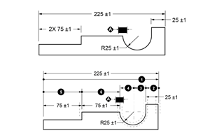
Tolerancing in Mold Design, Part 1: Understanding the Issues of Conventional Bilateral Tolerancing
Mold designers must understand the location, orientation and form limitations of conventional tolerancing before changing to another dimensioning system.
Read MoreWhat Is Scientific Maintenance? Part 1
Part one of this three-part series explains how to create a scientific maintenance plan based on a toolroom’s current data collection and usage.
Read MoreMold Design Review: The Complete Checklist
Gerardo (Jerry) Miranda III, former global tooling manager for Oakley sunglasses, reshares his complete mold design checklist, an essential part of the product time and cost-to-market process.
Read MoreLeading Mold Manufacturers Share Best Practices for Improving Efficiency
Precise Tooling Solutions, X-Cell Tool and Mold, M&M Tool and Mold, Ameritech Die & Mold, and Cavalier Tool & Manufacturing, sit down for a fast-paced Q&A focused on strategies for improving efficiencies across their operations.
Read MoreRead Next
Four Key 5-Axis Programming Developments for Moldmakers
Recent advancements in CAM software offer new benefits while maintaining ease of use.
Read MoreAre You a Moldmaker Considering 3D Printing? Consider the 3D Printing Workshop at NPE2024
Presentations will cover 3D printing for mold tooling, material innovation, product development, bridge production and full-scale, high-volume additive manufacturing.
Read MoreHow to Use Continuing Education to Remain Competitive in Moldmaking
Continued training helps moldmakers make tooling decisions and properly use the latest cutting tool to efficiently machine high-quality molds.
Read More



.jpg;maxWidth=300;quality=90)


