Practical Solutions To Common Machining Problems
Matching the roughing algorithm and tooling to the milling machine being used to machine the part is critical for high productivity.
Machining blocks of steel for mold applications is not the same as machining for production or other markets. Tools and software routines developed for other markets may haphazardly get the job done with regards to molds, but they may be a far cry from an optimized solution.
Following are some practical solutions to common machining problems specific to roughing operations in molds.
Plunge Roughing
Tooling and software has made great strides at taking advantage of high-speed mills, especially for finishing. Many of these high-speed mills are characterized by high spindle speeds and fast feedrates. Often, an older mill with high torque capabilities is still available, but the question is how best to utilize this capital equipment without creating work stoppages while one machine waits for another.
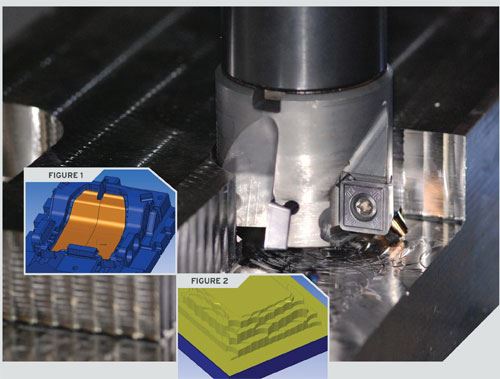
Plunge roughing often can have a metal removal rate that is double a traditional roughing operation. With all cutter forces along the axis of the cutter, and with intelligent dynamic stock modeling by a CAM system, this form of roughing is not only as safe as traditional roughing, but it can require less torque and increase insert life over traditional roughing.
Plunge roughing may not be the best solution for every part though. To perform the best plunge roughing you need parts with open areas of high volume removal.
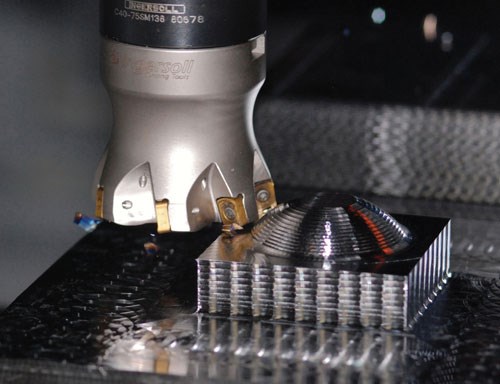
One perceived downside to plunge roughing is the condition of the stock after the roughing application. Plunge roughing, with a vertical cut and large forward step will leave larger stair steps of stock as compared to a traditional roughing application. However, both methods will require a re-roughing operation, both operations will have a similar amount of re-roughing cutting passes, just one will be able to take more material than the other.
When plunge roughing, the larger the forward step you take, the faster the material removal can be. Several tools are available that are well suited for plunge roughing, including many designed specifically for that purpose. Some cutters use a forward step up to ½ the cutter diameter and are available for smaller diameter plunge roughing needs. Other cutters are designed specifically for plunge roughing, with the cutting inserts installed in such a way that the insert material is supported for a plunge style cut, and support diameters from 1.0 to 6.0 inches.
Not all milling machines are capable of plunge roughing, often depending on the spindle design. However, there are still gains to be made from traditional roughing. There may be two different routes, often depending on the torque capabilities of the milling machine.
High-Feed Roughing
Cutting tool companies spend a lot of time and money in developing new cutter technologies that will allow for faster metal removal rates. New developments in cutting tool designs can allow molds to be roughed with either faster feedrates or larger depths-of-cuts. Cutting tool engineers have to be aware and design for the varying cutting conditions and loads found when roughing complex mold shapes. Sometimes the cutters will be cutting with 100 percent of the diameter, and sometimes only 10 percent, depending on the shape of the mold.
Some tools allow for higher surface footage when roughing steel as compared to traditional button cutters. This often translates into a larger depth of cut, a faster feedrate or a combination of the two.
When programming with these special cutters, it is important to take into consideration certain limitations when using those cutters. When utilizing a large diameter cutter, the area in between the inserts, or the non-cutting diameter becomes large, as a percentage of the overall diameter. It is important the CAM system is able to limit the cutter from trying to enter small pockets. Additionally, when ramping into pockets, it is critical the ramping motion, whether a helix or spiral motion, is large enough to accommodate the cutter geometry. CAM systems that employ a dynamic stock model are able to update the condition of the stock, at all times during calculation, thus providing cutter paths that are safe on the tool, yet also efficient for productivity.
Productivity is increased by using the larger depth-of-cut that this cutter is designed to handle. Roughing in this fashion is often done on milling machines with good torque capacities on the spindle. This is due to the large stepover that can occur, as well as the larger depth-of-cut that is available.
Torchoidal Roughing
Conversely, a milling machine characterized by lower torque capabilities and higher feeds, provides completely different problems for roughing. In this instance, using a form of torchoidal roughing can allow for fast feedrates without providing excessive load on the spindle. Torchoidal roughing is where the calculated cutterpath utilizes circular movements once the load on the cutter goes over a set amount. This keeps the cutter from ever cutting with 100 percent diameter.
When using torchoidal roughing, there are two very different approaches that can commonly be used on very high-feed machines. One option is to employ small step downs and large stepovers, say 50 to 70 percent of the cutter diameter. Once the stepover gets past 70 percent, torchoidal movements are automatically added. This approach uses the corner of the cutting tool for most of the cutting duties.
Another option for torchoidal roughing is to use a large step down with a very small stepover, maybe 10 percent or less of the cutter diameter. With this approach, you are effectively cutting with the side flutes of the cutter, instead of just the corner. It allows heat distribution along the tool, instead of having the heat concentrated right at the tip. This is sometimes referred to as peel milling.
Tooling with a 45-degree helix roughing tip can be used for roughing many materials. Utilizing the large stepover with the smaller step down and a torchoidal roughing movement, forces can be kept even. This allows for extended tool life.
Often when planning to use the small stepover and large step down (or peel milling) for roughing, one will use a solid carbide cutting tool. Cutters that have combo flutes of roughing and finishing can create a good chip control and further reduce cutting forces.
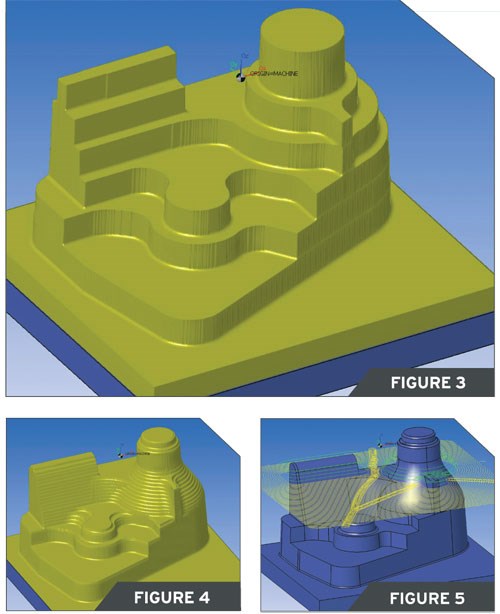
CAM systems that employ a dynamic stock model become critical when creating torchoidal cutterpaths. With a dynamic stock model, they will create torchoidal movements based on the actual load on the cutter, instead of a theoretical calculated load. Additionally, when peel milling, there will be larger stair steps of leftover stock. One advantage of the dynamic stock model is that the CAM system will know of those stair steps and automatically reduce immediately after the torchoidal roughing operation.
Summary
For the highest productivity it is important to match the roughing algorithm and tooling to the milling machine being used to machine the part. One size does not fit all.
Read Next
Plunge Milling Saves Time on Big Mold Cavities
By using a plunge mill, what used to take four hours now takes only 30 minutes—and stretches mold feedstock.
Read MoreReasons to Use Fiber Lasers for Mold Cleaning
Fiber lasers offer a simplicity, speed, control and portability, minimizing mold cleaning risks.
Read MoreHow to Use Continuing Education to Remain Competitive in Moldmaking
Continued training helps moldmakers make tooling decisions and properly use the latest cutting tool to efficiently machine high-quality molds.
Read More



.jpg;maxWidth=300;quality=90)


