Part 2: New Tool Concepts for Machining Dies and Molds
The use of multifunction inserts is a significant geometrical development - making it possible to machine various operations with a single insert.
Last month, the first half of this article (New Tool Concepts for Machining Dies and Mold, April 2002) addressed some basic tool concepts. This month, the article will expand on that and address milling tools, endmills and inserts for drilling geometries.
Face, Slot and Shoulder Milling Tools With Various Geometrical Concepts
The helical-cutting-edge insert idea used today with a variety of cutters for dies, molds and housings, including facemills and endmills, is shown in Figure 15.
 |
| Figure 15: A selection of face, shoulder and heavy-duty endmills. |
Even endmills with small diameters - normally made of solid carbide, of HSS or brazed carbide - can be equipped with these inserts. The helical inserts are screw-clamped on single-row endmills for small depths of cut; on endmills with internal flushing with improved chip exit; on long-shank cutter bodies for deep cavities with high stability due to the helical insert design; and on the heavy-duty cutters for deeper shouldering and slotting operations. The more positive radial rake and the larger axial angle provide improved stability and lower forces for machining with large overhang and in deep slots.
The helical inserts are used to their maximum depth with their side cutting edge for side wall or 90' shoulder machining while the frontal wiper in this case provides excellent surface quality. The same insert, when clamped in a face milling cutter with 75', uses the two additional corners with the strong 94' angles for facing operations. The option to apply all four corners of this unique insert design - two for shouldering and two for facing - offers optimal economy in use.
In order to provide a full-effective cut - which means that each flute will cut with its full length without steps - heavy-duty cutters are designed with overlapping helical inserts. In this way, a full-effective cutting edge is created. The large right-hand helical angle of each insert and the stepped, larger axial angle of the flute insures easy chip exit and a step-wise, softer penetration into the workpiece - improving stability and reducing cutting forces.
 |
| Figure 16: Square helical inserts for (A) ramp down, (B) roughing of cavities, (C) side wall and (D) slotting applications. |
The square inserts with four effective helical cutting edges are used for various operations. Figure 16A shows a ramp down operation by an endmill. The ramp down operation can be done with an up-to-30' slope depending on the tool diameter. Side wall machining of deep cavities with a heavy-duty cutter for higher removal rates is shown in Figure 16B. Figure 16C shows a deep shoulder roughing operation with a heavy-duty tool. Both tools in 16B and 16C use overlapping inserts with full-effective flutes to enable higher productivity. In Figure 16D, a slotting cutter with square symmetric inserts is shown. The insert geometry insures higher corner strength, and the symmetrical design balances the axial forces.
 |
| Figure 17: Square inserts with four cutting edges for various cutter options. |
A selection of square inserts for various endmills, face-, shoulder- and T-slot-cutters is shown in Figure 17. The octagonal inserts can be used for a wide range of applications in machining dies, molds and housings.
 |
| Figure 18: The multifunction milling option with octagonal and round inserts. |
Figure 18 shows a variety of options with the octagonal inserts and with the round insert mounted on the same cutter body. Operation A is facing at low forces, small depth of cut and good surface quality. Operation B is a deep, plunging operation in which the frontal, the side and the 45' cutting edges are active. Step C shows plunging and facing - each step at 3.0 mm depth. It can be used to machine cavities in any required form to remove large volumes of material. This operation also can be done with a spiral tool movement, especially when the dimensions of the cavity are much larger than the tool diameter. Operation D represents machining of a slot with a round or shaped profile. Option E represents 45' slotting steps; Step G is a side shouldering operation; and the final Step F is a chamfering operation making use of the 45' cutting edge configuration.
 |
| Figure 19: Profile milling of three-dimensional surfaces and deep cavities with full-radius inserts. |
These plunging and profiling options are shown also in Figure 19. Figure 19A shows a deep cavity machined with a round insert clamped on the same cutter as used with the octagonal insert. In this case, plunging in 3.0 mm steps and facing was used. A rough profiling application of a large surface is shown in Figure 19B. The round insert possesses very positive rake angles, almost sharp cutting edges - possible because of the PVD-coated grade used - and depression-type rake face to reduce contact with chip flow, resulting in less heat, lower wear and improved tool life.
 |
| Figure 20: Multifunction milling cutter with a selection of inserts. |
The development of new multifunction milling tools, especially for industries in die, mold and housing production, is designed for greater economy and versatility in milling, simplicity in tool selection and reduction of tool inventory (see Figure 20). New multifunction cutter design used for a wide variety of facing, shouldering, shallow face milling and profile milling applications enables the use of a single cutter with a selection of inserts for most cost-effective milling.
The described milling line is based on a pocket in which various insert shapes can be mounted. The pocket geometry on the cutter is designed with three contact points for clamping that insure radial and axial insert positioning. In the unique pocket configuration, octagonal, round, square and 45' facing or chamfering inserts can be mounted. By using the various insert shapes, different lead angles for various machining applications can be covered.
The same star-shaped insert base is used for mounting and securely indexing inserts in four and/or eight mounting positions. The recommeded types of inserts include inserts with four corners for 90' shoulder milling; inserts with four-corner 45' facing operations; the full-radius inserts used for facing, slotting or profiling; and the octagonal inserts with eight 45' cutting edges for high economy. Due to the star-shaped base, the inserts can be rotated to a maximum of eight positions for increased economy, as shown in Figure 18.
Endmills and Inserts for Profiling
As shown in Figures 18, 19 and 20, tools with indexable inserts can be used for facing, shouldering, slotting and profiling of large surfaces in roughing and semi-roughing of housings or cavities of die and mold shapes. The use of these tools for finishing operatons is limited due to surface quality requirements, run-out of the tools, adjustment limitations, cutting edge configurations and the very small feeds and depths of cut used. Furthermore, when high side-wall flatness and accuracy is required, the use of extended flute cutters with multiple inserts is limited. In all of these cases, endmills - either solid or with single indexable inserts with various configurations made of various cutting tool materials - can be used. The solid endmills are made of HSS and coated HSS, as well as submicron carbides, CBN or PCD tips brazed on steel bodies ground to final dimensions.
 |
| Figure 21: Endmills with ballnose and with 90' square shapes with various cutting-corner geometries |
Figure 21 shows, for example, solid carbide endmills with square and ballnose shapes made of submicron substrate and high quality TiAlN- and TiCN-PVD coated layers.
All modern carbide endmill cutters are made of submicron substrate with improved toughness and hardness, better resistance to cracking or chipping, and high wear resistance. This combination of substrate and PVD coating properties provides excellent, high performance in a wide range of applications. New endmills - uncoated or with the unique PVD-coating - have sharp cutting edges and high resistance to impact and interrupted cutting action.
Endmills are available in standard square geometry, which means an almost 90' sharp corner (EC) and premium geometry with a unique, chamfered corner (ECC) designed to eliminate fracture and extend tool life. Standard and premium endmills are produced with two, three and four flutes for 90' shoulders according to DIN 6527-6528, and center cutting tools with cylindrical shanks in the diameter range from two to 20 mm.
Ballnose endmills are available today in a wider range of diameters and a selection of ground cutting-edge options. The high-helix three-flute slot drills are used especially for high-temperature alloys, stainless steel and nonferrous materials.
Two- and three-flute endmills can be used for pocketing and slotting when larger chip gullets are required to insure good chip evacuation. The three-flute cutters instead of the two flutes are mainly used for slotting and pocketing where more stability is needed as well as at higher feeds. These cutters also are available for contouring.
The four-flute cutters are used for contour finishing where a fine surface finish or increased rigidity is needed, and at higher feeds.
The chamfered premium line also includes solid carbide endmills with four flutes for contouring, available with the PVD TiAlN and TiCN coatings. The TiCN coated tools are recommended for most of the standard applications in machining alloy steel and tool steel materials. The TiAlN coated tool is an excellent grade for hard machining, machining without coolant and on high-temperature alloys. The machining of dies and molds made of alloy steel in the soft and hardened state with the new PVD-TiAlN coated tools improves tool life significantly. For example, in milling a 1.2379, AISI D2 hardened steel die with 50HrC, with a 10 mm diameter endmill, the tool life of the submicron endmill and the TiAlN coated grade was much higher compared to the TiCN coated endmills. Cutting speed was 60 m/min.
 |
| Figure 22: Tool life of various solid carbide coated submicron endmills. |
The endmills tested possess a large helix angle of 30' with reduced cutting forces and improved stability. As the frontal cutting-edge corner is subjected to higher impact, the 90' almost-sharp-edged tool (EC) and the tool with the unique chamfered-edge configuration (ECC) were tested. Comparison of tool life (machining time) of the EC and ECC types, both with PVD coated TiCN layer, to the ECC type with TiAlN coating is shown in Figure 22.
The tool life of the ECC endmill geometry with TiAlN coating, for a wear land of VB = 0.2 mm, was doubled compared to the EC sharp-edge type with a TiCN coated layer. In some cases, the use of sharp corners is essential due to the workpiece configuration and, therefore, standard EC endmills are used.
 |
| Figure 23: Endmills for high-speed milling of molds and dies. Diameters range from eight to 25 mm. |
Indexable inserts for endmills with a conical hole and the horseshoe design for clamping were shown in Figures 7 and 8 from last month's article. A selection of the endmills for these inserts is shown in Figure 23.
 |
| Figure 24: Ballnose and extended flute ballnose endmilss for roughing applications. |
In Figure 24, ballnose end-mills with larger diameters as well as endmills with extended flutes for heavy-duty profiling are shown. These types are used for rough milling and machining of the deep round shoulders required in machining molds and dies.
Two main types of cutters in the diameter range of 32 mm up to 63 mm are offered. The first, the CM type, can carry three or four double-sided, curved inserts to perform a complete circular geometry. The insert screw-clamping area is V-shaped to insure secure, strong, wedge-type clamping without requiring high tightening forces. The insert design provides a slanted flank to reinforce the cutting edge and two strong cutting edges - one each for left- and right-hand directions.
The two identical inserts - acting simultaneously - provide two effective flutes for higher productivity. The design of the insert rake face and cutter with positive geometry requires less machine tool power.
The second cutter type, the CMK, is equipped with an extended-flute geometry while maintaining the same frontal ballnose insert as used in the CM type. In additon, four ANKT negative inserts are positioned on each of the two flutes. The unique negative design of the ANKT insert, clamped above center, provides the required clearance angle and very strong, safe clamping of insert in seat. This special combination insures that the cutting forces act in the direction of the cutter body center, providing full support for the cutting edge, and, therefore, enabling the use of smaller clamping screws and lower tightening forces.
Balancing of the cutting forces is achieved by the left-hand helix of the ANKT inserts, while the frontal curved inserts are positioned at a right-hand helix. The maximum depth with the CM type is 20 mm; the maximum depth of the CMK is 44 mm.
In machining of dies and molds, the first step is roughing and the second is finishing. While roughing, the question is how to increase cutting area per hour. In finishing, the main and essential problem is the surface integrity.
 |
| Figure 25: High surface quality in finishing with double-edged, ground inserts. |
When using inserts with the CR, configuration up to a depth of cut ap = 0.8 mm, only one cutting edge is in action. Therefore, it is recommended only for semi-finishing conditions. When a superfinish surface quality is required, the two-effective cutting-edge insert (CRF) should be preferred (see Figure 25). The cutting edges are ground sharp, rake face is positive and the frontal centerpoint is slightly below the tool center to insure soft cuts. The results with this CRF ground insert can produce very high surface quality with about Ra 0.1-0.2fm.
 |
| Figure 26: Rough and semi-rough milling of blow molds for bottles. |
An example for the machining of blow mold parts is shown in Figure 26. The material is stainless steel AISI 420 with about 50 HrC. For roughing, the CM-D32 tool type with TiCN PVD coated inserts was used at higher machining rates and stable operation. The shown finishing operation of the bottom profile was done with a solid carbide endmill, 6.0 mm diameter, two flutes and the TiAlN coating. After finishing, only a short hand polishing was necessary. In cases when hardened steel (>HRc) is machined, the CBN tipped endmills are used. This is the case of forging and casting dies machined after being hardened. The cutting edge is slightly honed or a small (0.2 to 0.3 mm) negative land (15' to 20') is used.
 |
| Figure 27: Three unique types of drills for high performance drilling in the range of 16 to 55 mm. |
Insert Geometry in Drilling
Today, the development of drilling geometries with indexable inserts is probably the most interesting direction to replace HSS, brazed carbide-tipped drills - and even solid carbide drills. Some drills are using standard indexable inserts, some are equipped with trigon, single-sided inserts, and more and more versions are using unique geometries to improve performance and tool life. Figure 27 shows, for example, three new drill types. The first for smaller diameters (16 to 35 mm) is a drill with two square, slanted helical inserts in which the frontal cutting edge is sloped crossing the center of the drill. The positive rake angle on each of the cutting edges enables a soft and easy chip flow. The design of the drill body was done by using the finite-element method in order to balance radial forces, torque and deflection. Various chipformer types for different materials are available. Some are more positive for easier chip flow on soft materials like aluminum or stainless and are designed for low feeds, and some are designed for high feeds on various steel types.
 |
| Figure 28: Serrated insert with frontal leading edge for high performance, chip splitting and improved surface quality in drilling. |
The second drill type is equipped with a serrated cutting edge, providing chip separation and easy chip flow during drilling (see Figure 28). This ease of separate chip flow enables higher feeds, longer tool life and protects the drilled hole from damage. The corner design provides more strength and is used with the wiper to improve surface quality.
The third drill type uses a double-sided, trigon insert with a concave clearance face to enlarge clearance angle and to provide the possibility of using all six cutting edges for more economy. The chipformer is a rib-type deflector reducing contact between rake face and chip and decreasing friction, heat and wear.
To date, the drilling of small holes (up to 15 mm) - which is the largest application range - has been done mainly with HSS brazed or solid drills. It has always been very difficult to design, produce and use drills with indexable inserts in the small diameter range, mainly because of clamping problems. Today, more and more drills with screw-clamped inserts are being introduced.
An example of a unique system using a simple, fast-clamping feature of a dove-tail shaped insert (head) - which is replaced after wearing out and fits into the corresponding pocket in the drill body - is shown in Figure 29.
 |
| Figure 29: Drills with self-clamped indexable inserts (heads). |
Indexing and clamping of the drilling head is done without removing the drill body from the machine tool. The wedge-type, dove-tail clamping device causes strong axial back-pulling forces to secure clamping during machining. The drilling head design without any screw or clamping device enables larger gullets for better chip evacuation.
Four different drilling head types are offered with different cutting edge configurations optimized for various drilling applications.
For standard drilling, the frontal edge is 140' with a small central web and is recommended for use on dies, molds and housings made of carbon steel and alloys, and other steel types. The second type are heads with a 90' frontal-edge, recommended for chamfering and spot drilling. Furthermore, this type - with its ground rake face surface and sharp cutting edges - is recommended for softer materials, like nonferrous and nonmetallic types. The flat indexable drilling head is used to machine flat-bottom bores, especially when face-countersinking is required. For spherical cavities, the full-radius head is used.
This new drilling concept and similar products with flexibility of drilling head shapes offers an excellent solution for small-hole drilling operations used in large volume in die, mold and housing production.
Summary
The development and introduction of new insert and tool geometries for machining dies, molds and housings is an ongoing process improving performance, tool life, surface quality and economy. The use of new clamping devices makes it possible to reduce insert size, provides stronger clamping, guarantees more insert strength, reduces cutting forces and required power and saves indexing time. The use of multifunction inserts is the most significant geometrical development, making it possible to machine many, various operations with a single insert, reducing the number of inserts on the turret, and in the warehouse. Optimization of the insert and chipformer geometry in milling, drilling, and profiling improves accuracy of the machined surface, provides more tool life, reduces cutting forces and vibration and makes it possible to control chip shape and chip flow.
Related Content
Modular Tooling Systems Enable Versatility in Hole-Drilling Operations
The versatility of replaceable cutting edges offers users the ability to adapt to varied operations.
Read MoreThree Ways to Accurately Machine Hardened Mold Materials
Three cutting tool design considerations to improve process reliability and cost efficiency when deep-hole drilling molds.
Read MoreHow to Overcome Cutting Tool Vibration
Advanced indexable milling cutting tool design provides secure, predictable machining, increased metal removal rates, reduced cycle times and fast changeovers.
Read MoreHow to Use Continuing Education to Remain Competitive in Moldmaking
Continued training helps moldmakers make tooling decisions and properly use the latest cutting tool to efficiently machine high-quality molds.
Read MoreRead Next
Milling Toolholders Reduce Vibrations
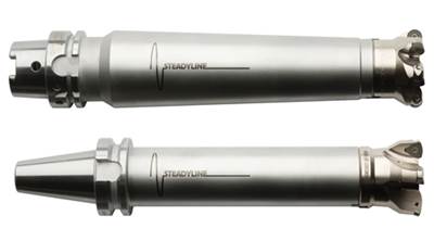
Although long-overhang tools can reach deep cavities and other difficult-to-access areas, such cutters can introduce vibration into the machining process. To address this issue, Seco Tools’ Steadyline vibration-damping shell mill holders feature a passive dynamic damping system that offers as much as 3× the rigidity of common solid holders.
Read MoreHow to Use Continuing Education to Remain Competitive in Moldmaking
Continued training helps moldmakers make tooling decisions and properly use the latest cutting tool to efficiently machine high-quality molds.
Read MoreHow to Use Strategic Planning Tools, Data to Manage the Human Side of Business
Q&A with Marion Wells, MMT EAB member and founder of Human Asset Management.
Read More


.png;maxWidth=300;quality=90)




.png;maxWidth=970;quality=90)