Machining 3D Parts
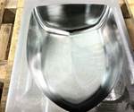
For most of the 3D machining required in moldmaking, there are essentially seven steps necessary to achieve the desired results in terms of shape, finish and cycle time.
Three-dimensional (3D) machining has transformed over the last 20 years from what some might have once considered just “magic” into a structured process. In fact, for more than 70 percent of the 3D work required in moldmaking, there are essentially seven steps necessary to achieve the desired results in terms of shape, finish and cycle time. For the remaining work, part shape determines which of the seven steps need to be followed.
Step one in the process is roughing, and following certain associated rules ensures the success of all subsequent steps. Three-dimensional machining is like a relay race in which the success of the whole depends on how each process step sets up the next one for outstanding results. In the roughing stage, following the set guidelines for depths of cut will bring the part close to net shape so the next tool will not struggle. Typically, this stage takes anywhere from 5- to 10-percent depths of cut, depending on material hardness. Marrying the depths of cut, feeds and speeds, and a programming technique that includes smoothing of the toolpath yields a reliable, repeatable process.
Step two is re-machining with a smaller tool in areas that the first tool could not reach and machining corners even closer to net shape. Most companies struggle with this step because they are accustomed to moving incrementally from large roughing tools to smaller and smaller tools to remove material. The re-machining approach requires, for example, a move from a 1-inch tool immediately to a ¼-inch tool. Cutting tool sizes in between are not necessary, because today’s 3D software packages use a stock model to identify material location after each tool run.
A good rule of thumb for the re-machining step is to use a tool with a diameter that is 25 to 30 percent of the initial rougher diameter. By driving in the corner and referencing each tool path to the previous one, the location of the stock is always known. This technique also maintains efficient programs because the tool is in the cut as opposed to having too much air time bouncing around.
Step three in 3D machining is scanning the part’s low-lying areas. In Z-level roughing of 3D parts, the flat, low-lying areas end up with large scallops or cusps. Scanning across the low-lying areas allows these scallops or cusps to be removed and will not interfere with the remaining tools yet to run.
These first three steps in the 3D machining process must be followed in order to produce optimal machining results. The remaining four steps—which will be discussed during Amerimold’s “Step by Step Process to Guide Your Approach to Programming 3D Parts” workshop on Thursday, June 18—will yield a beautiful finish on an accurate part. Register Today! If you cannot attend the event, look for a follow-up online after the show.

Related Content
-
Mold Design Review: The Complete Checklist
Gerardo (Jerry) Miranda III, former global tooling manager for Oakley sunglasses, reshares his complete mold design checklist, an essential part of the product time and cost-to-market process.
-
How to Fix Predicted Warpage Before It Happens with Windage and CAD Model Morphing
Applying windage and model-morphing techniques saved toolmaker/molder Sturgis Molded Products the time, cost, headaches of multiple part/mold design iteration loops, cumbersome cooling fixtures, and long molding cycles.
-
How to Improve Your Current Efficiency Rate
An alternative approach to taking on more EDM-intensive work when technology and personnel investment is not an option.


