Innovative Hot Runner Solutions for Ultra Small Parts
The injection molding of micro parts calls for innovative hot runner solutions to comply with the demands of injection molders and toolmakers.
The injection molding of precision and micro parts creates special demands on the moldmaker and hot runner supplier. Since the weight of the parts ranges from 0.05g to 2g the weight of the runner system has an increasing influence on part price. Due to the fact that most tiny parts have to be produced with very small tolerances, it is necessary to use a naturally balanced runner system to achieve uniform filling of the cavities.
With a solidifying runner system, the weight of the runner is many times the weight of the part. This creates high material costs per part and necessitates additional equipment to separate the runners from the parts, thereby increasing the total part price.
On the other hand, the use of a conventional commercial hot runner system will increase the mold size and also the mold costs because of the size and number of nozzles required to inject the parts directly. To reduce mold and material costs, a fully balanced hot runner for a large number of cavities with fewer control zones and a small pitch is required.
Balancing with the Smallest Pitch Dimension
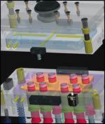
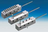
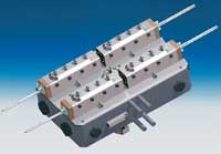
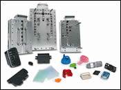
In a mold for small parts the pitch dimension of the hot runner tips determines the mold size. To reduce the size it is necessary to screw the tips directly into the manifold. The natural balancing is achieved by a special distribution device. Figure 1 shows hot runner systems for 4-, 8- and 16-drop applications. The internal distribution of the melt is shown in Figure 2. A radially milled cylinder distributes the melt to each tip with the same flow length. This concept allows a fully balanced hot runner system in limited space.
With technical resins—particularly those containing flame-retardant additives—it is very important to achieve a short residence time of the material in the manifold. Lower pressure loss and short residence times actually contradict each other. For a lower pressure loss a large flow is required and for short residence times a small flow channel. With the externally milled manifold cylinder it is possible to create the channels in a way that enables a compromise to be achieved between these two features.
With critical materials it also is necessary to calculate the residence time and the pressure drop in the system. There are many of calculation programs on the market that can help to pinpoint the best compromise.
The cylinder is mounted on the body of the manifold and heated by a cartridge at the center. Minimal tolerances and accurate manufacture—together with special sealing plugs—make sure there is no leakage in the system.
The Influence of the Temperature Profile to the Part Quality
The degradation of the material depends not only on the dwell time, but also on the temperature profile of the hot runner components. The permitted temperature range of the processed plastics should not be exceeded to avoid a degradation of the material in the manifold.
For this reason a uniform temperate profile along the manifold is absolutely essential. In hot runner systems there is always a certain heat transfer from the heated components into the mold.
There are three types of heat transfer to the mold:
- Radiation
- Convection
- Heat conduction
All these types of heat transfer have to be reduced to a minimum. In the case of radiation, this means giving the manifold a surface similar to a white emitter. With convection, it is important to keep the clearance small, and with heat conduction to ensure minimum contact surface.
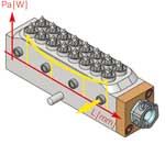
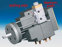
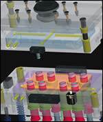
Figure 3 shows a 16-drop manifold with special titanium elements to reduce the heat conduction and an optimized heater profile to even out the heat transfer by radiation. At both ends of the manifold the heat transfer by radiation is higher than in the middle of the manifold, which means that more energy needs to be placed at the ends of the heating cartridge than in the middle.
Mold Design for Mini Hot Runners
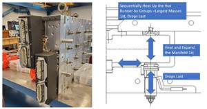
As previously mentioned, reduced heat transfer into the mold can be achieved by minimizing the contact surfaces between the mold and hot runner. The melt chamber is sealed at the front surface of the surrounding titanium rings. This compensates for the heat expansion of the manifold and avoids tension caused by heat expansion. The loaded face has minimal compression and therefore reduces the lifting power. The small volume of material in the gate chamber area facilitates quick color change and short dwell time.
The manifold must be located at its center to achieve a uniform heat expansion in all directions. The small pitch of the tips allows very precise calculation of the heat expansion and makes small gate diameters of 0.4mm possible.
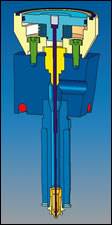
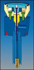
The tips should be made of a material that shows a good compromise between wear resistance and heat conductivity. Special molybdenum alloys can be used to achieve this. If all the guidelines of mold design are taken into account, high quality parts with minimal gate markings can be produced with a mini hot runner system on small machines (see Figure 4).
There many applications for using mini hot runners in molds. They can be used with very small machines like the baby plast or under a distribution manifold that feeds four sub manifolds. See Figure 5 for an example.
The possibility of combining the mini hot runners with standard manifold components offers a wide variety of mold concepts. Despite the minimized control zones and the simple implementation, the use of hot halves guarantees a correctly mounted system and avoids problems at the start-up of the mold.
Summary
The continuous progress made in hot runner development is offering moldmakers and injection molders new solutions that will enable them to stay competitive in the changing market.
Related Content
The Ins and Outs of Hot Runner Temperature Control
A training checklist that explains the why and how of proper hot runner temperature control and system management.
Read MoreHow to Overcome Five Common Hot Runner Cable Connection Problems
Here are some simple solutions for pushed-back or bent pins, pushed-back inserts, high amp deterioration, loose or broken latches and missing or loose ground wire connections.
Read MoreHow to Maintain Heaters, Thermocouples, Valve Gates and Controls
An examination of real-world problems and solutions involving hot runner system maintenance.
Read MoreHow to Use Hot Runner Balance in Mold Qualification
If you are interested in the impact of system and hot runner balance on part quality, the causes of unbalanced hot runner systems and short shot parts, the procedure for measuring system balance and the impact of application specifics on system and hot runner balance expectations, then tune into this on-demand webinar.
Read MoreRead Next
Evaluating Gate System Designs
A hybrid gating option combines the advantages of valve gate and thermal gate systems.
Read MoreHot Runners Shrink Leadtimes, Cut Costs
Standardized hot runner system allows the moldmaker to easily configure a system in just two weeks.
Read MoreDon’t Build the “Same Old Same Mold”
Steps for evaluating the latest mold innovations in order to move along the evolution process.
Read More
