Expanding Business Opportunities With Five-Axis Software
Moving to five-axis machining may seem a daunting maneuver, but with the right software and training, a moldmaker can gain an advantage on the competition.
Five-axis machining is becoming a way of life for some operations. In fact, for an increasing number of plastics manufacturers and machine shops that do moldmaking and subassembly fabrication, five-axis machining can make existing work run faster and more accurately. Also, the complexity of some molds, prototypes and parts now demands five-axis work. Investment in the technology and software can become a sound business decision resulting in an increase in orders or an expansion of product offerings. Companies also can enter market niches which require greater precision and become even more competitive based on faster turnaround with some five-axis-based processes.
The Extra Axes
Five-axis toolpathing and machining combines the movement of the machine head in the usual x-y-z directions with the ability of specialized machines to alter the angle and movement of the machining head and/or the table. For example:
- When the head is rotated in an arc on the X axis, it is rotating in the A axis - and is still programmable for concurrent motion in the x-y-z directions. This is often associated with gantry mills, mills with rotary tables and hexapod tables. The hexapod is capable of moving the table relative to the x-y-z axes.
- When the part or head rotates about the Y axis, it is moving in the B axis, again while still following programming in the x-y-z directions. Machines with a wrist configuration in the shaft will angle the spindle to achieve B-axis orientation.
- Rotation of the C axis - turning (or circling) the workpiece along the axis parallel to the spindle - is most easily achieved with a rotary table. Some machines - the gantry in particular - are capable of indexing the entire milling mechanism about the Z axis.
- For certain complex work - undercutting, for example - the tool is fixed at angles in the A and B axes and cutting proceeds in the three-axis format. This variation is often called 2+3 machining.
Learning Five-Axis Programming
Assuming that they already know three-axis programming, most technicians should be able to be production-ready in a couple of weeks. It should only take a couple of days to establish machine coordinate positions for fixed A and B rotations and setup of various tooling for some machining centers, such as a rotary-A, rotary-B machine, which allows the operator to flip the A-axis rotary head orientation 90' to create a working C-axis configuration.
Some suppliers will offer workshops to review multi-axis options, as well as the setup and programing of five-axis machines. After another week or so of using the software and referring to the classroom materials in-house, operators should have the experience and confidence to begin programming multi-axis parts.
The most important step in five-axis machining is to position the part in the software relative to where it actually sits on the machine. The part is secured to the machine; the spindle moved over a locating hole, a corner or some other accurate marker; and the location (X2, Y3, for example) is set from the machine's 0-0. The programmer moves the part in the software so that the setup point used is now referenced to the same position (X2 Y3) by the program. Now the machine's 0-0 and the software 0-0 are the same - the part 0-0 is actually X2, Y3.
Five-Axis Programming in Practice
An example of two five-axis variations used to produce parts occurred when secondary school classes in Illinois were unable to find stock ring gear-and-pinion parts to conform to the design for their entry in a nationwide BattleBots competition - a cable TV show where participants build robots to fight for prizes. The description of these operations is far more complex than performing the programming itself, as a good five-axis software program should simplify programming.
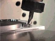
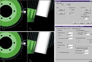
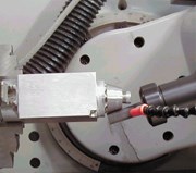
The steel pinion was first up on the machine. Cutting the angle of the pinion lands was a modified three-axis job in that the tool was indexed in the B axis to keep the tool normal to the angle of the pinion gear's finish surface in order to swarf-cut the basic gear shape (see Figures 1 and 2). It is best to cut as much material as possible with three-axis movement because it allows for larger tools and deeper cuts. At the roots of the pinion gears, modified three-axis was still used, this time also indexing in the A axis, for a 2+3 combination (see Figure 3).
Indexing the head was mandated by having to use a .032" ball nose endmill to cut the .016" radii at each root. Given the flute length and tool shank size, it was necessary to specify a line vector to create a construction plane normal to the direction in which the tool should run in order to avoid contact with part surfaces.
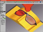
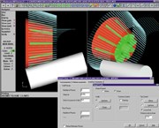
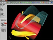
Cutting the ring gear outside the diameter relief began as a three-axis constant Z roughing routine with a flat endmill, which left a series of stair-steps. It was then necessary to define the upper and lower contours (see Figure 4) for the tool to follow and cut using a 1/4" flat mill, which transitioned between the two contours. Finish cutting of the outside diameter relief of the ring gear required true five-axis machining (see Figure 5). Because of the tool limitations when cutting the hardened steel, it was best to cut the .100" down to the finish depth of the gear walls in two depths, making three passes each at .002" - picking at it three times to half-depth, then picking three more times to the end.
Programming the passes consisted of using the user interface to select three wall cuts and two depths of cut from available parameters. This was programmed by entering the values "3 at .002"" and "floor passes" at two. Since the program already knows the size and placement of the walls and floor, it automatically calculates the desired toolpath vectors.
Five-Axis Advantages
Initial five-axis fixturing takes somewhat longer than for simple three-axis machining. But those who have machined complex molds or forms in the three-axis mode by refixturing the workpiece for clear access and tool clearance know that considerable time is consumed not only by the physical operation but in offsetting the CAM software to a new Y0, X0 - for each move. This is especially true when working with mold designs requiring undercutting from a variety of angles. Multiple refixturing is wide open to locating errors, compounded with each setup. Accuracy can suffer, with attendant time and material losses increasing. From that viewpoint alone, one-time five-axis fixturing saves time and cuts the production cost for the entire project.
Accuracy and production time are enhanced with five-axis use in some vacuum forming operations as well. Production speeds up with five-axis-based parts trimming, especially when designs call for the trim cut to be perpendicular to flow lines, curves, splines and other surfaces. Short of hand-trimming and finishing, three-axis would be hard put to accomplish the job without either making multiple passes or leaving a stepped finish - which would still require handwork.
What Is the right machine for you?
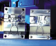
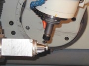
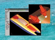
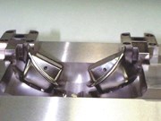
Optimum machine configurations vary by companies' general job lines. Impeller/ propeller prototypes (see Figure 6) and production work are virtually impossible without five-axis capability - best configured with a rotary table/tilting (wrist) head. Many complex molds (see Figures 7, 8 and 9) are prime candidates for five-axis machining, as are many jobs for the aerospace and automotive industries.
Prototypes and final molds for large vacuum formed products (see Figure 10) call for a gantry-mounted mill - the same five-axis capabilities on a larger scale: large table, extended tool travel and greater overall clearances. The same machine can do production duty to give a fine final trimming finish. The gantry's scale also is well suited to cutting molds for the fiberglass industry - boat-building, plumbing fixtures and similar product lines.
Cost Versus Production Gains
As size, complexity of configuration and options increase, purchase costs rise. How much to invest must be balanced by each company's projection of the costs saved or business potential increased. Generally, a shop could expect to pay upwards of $50,000 more for larger five-axis units than for similar three-axis machines. For makers of small-to-moderate sized molds, this lower price could be an entry into the five-axis world. A basic five-axis wood router can run from $100,000 to $200,000. The step up to larger, more complex machines is pricey, with costs reaching $400,000 - larger machining centers and gantry mills can run into the millions.
The variety of available machine configurations and the requirements of each shop's clients demands time well-spent with representatives from several vendors seeking the best configuration/production combination. One key indicator for a five-axis upgrade is the number of jobs you are currently refixturing. If your closest competitors are using five-axis machining, you can compete better; if not, you can beat them on turnaround and precision.
If your business examination justifies a five-axis purchase, and you have the capital or credit line to invest, be not afraid. Just as the machine company's tech reps will help with training and support, software also is readily available from suppliers, as is training and ongoing software support. With all that going for you, capitalizing on five-axis will be limited only by your imagination and entrepreneurial spirit.
Related Content
Making Mentoring Work | MMT Chat Part 2
Three of the TK Mold and Engineering team in Romeo, Michigan join me for Part 2 of this MMT Chat on mentorship by sharing how the AMBA’s Meet a Mentor Program works, lessons learned (and applied) and the way your shop can join this effort.
Read MoreDynamic Tool Corporation – Creating the Team to Move Moldmaking Into the Future
For 40+ years, Dynamic Tool Corp. has offered precision tooling, emphasizing education, mentoring and innovation. The company is committed to excellence, integrity, safety and customer service, as well as inspiring growth and quality in manufacturing.
Read MoreTackling a Mold Designer Shortage
Survey findings reveal a shortage of skilled mold designers and engineers in the moldmaking community, calling for intervention through educational programs and exploration of training alternatives while seeking input from those who have addressed the issue successfully.
Read MoreMMT Chats: It’s Time to Play … The Moldmaker Card Game! Yes, a Game to Educate and Entertain
MoldMaking Technology Editorial Director Christina Fuges connects with Professor Steffen Ritter from Reutlingen University in Germany about the card game for moldmakers he developed to help promote and educate our next generation of moldmaking professionals in a fun way. This episode is brought to you by ISCAR with New Ideas for Machining Intelligently.
Read MoreRead Next
How to Use Continuing Education to Remain Competitive in Moldmaking
Continued training helps moldmakers make tooling decisions and properly use the latest cutting tool to efficiently machine high-quality molds.
Read MoreAre You a Moldmaker Considering 3D Printing? Consider the 3D Printing Workshop at NPE2024
Presentations will cover 3D printing for mold tooling, material innovation, product development, bridge production and full-scale, high-volume additive manufacturing.
Read MoreReasons to Use Fiber Lasers for Mold Cleaning
Fiber lasers offer a simplicity, speed, control and portability, minimizing mold cleaning risks.
Read More




.jpg;maxWidth=300;quality=90)


