Machining Graphite Using Diamond-Coated Tools Part 2: Guidelines and Results
When machining long rods and cylinders, higher speeds and depths of cut can be employed with higher strength graphite materials.
Turning Graphite
Disposable inserts with a 1/64- to 1/32-inch nose radius are most effectively employed for turning graphite. A positive rake insert without a chip control groove is preferred. Cutting fluids and/or coolants are not recommended. Adequate and well-maintained fixturing, rigid tool setup and well-adjusted machine tools always provide superior results.
When machining long rods and cylinders, higher speeds and depths of cut can be employed with higher strength graphite materials. Depth of cut should always be maximized when possible without incurring distortion of the part. When distortion or whip are present, feed and depth of cut must be adjusted. Lower feedrates will allow holding deeper cuts. Feedrates of 0.005" per revolution for roughing and between 0.001" - 0.003" for finishing might be necessary. Deeper cuts always generate higher pressures and larger fracturing particles, thereby producing rougher surface finish.
Machine setup and measurements are best done with non-contact of the diamond cutting edge. This includes use of a soft material such as plastic or paper for touching off. Cutting edge contact with any hard material prior to cutting potentially will damage the edge.
Breakout at the end of a pass is always a concern. This can be avoided by having a chamfer cut at the end of the part to ease exit of the tool, or provide stock which can later be cut off. Avoid square-nosed cut-off tools to avoid breaking prior to completion of the cut. A 20-degree angle is recommended. Surface finish improvements can be achieved with tool geometry combined with feedrates. Larger nose radii will produce improved finish but with increased tool pressure. A smaller nose radius will relieve pressure, but feed must be lessened to achieve comparable surface finish. Depth of cut will not affect surface finish unless it causes excess tool pressure - resulting in vibration - or if it is too light (under 0.005") to create an adequate amount of material removal.
Milling Graphite - Inserted Cutters
Most information for turning graphite applies to milling with inserted cutters. Disposable inserts with a 1/64" or 1/32" nose radius are most effectively employed for milling graphite. A positive rake insert is recommended. Cutting fluids and/or coolants are not recommended. Adequate and well-maintained fixturing, rigid tool set-up and well-adjusted machine tools always provide superior results.
When milling large surfaces or volumes, higher speeds and depths of cut can be employed. Use higher strength graphite materials when there are thin walls involved. Depth of cut should always be maximized when possible to eliminate multiple passes. Lower feedrates will allow holding deeper cuts. Feedrates of 0.004/tooth/revolution for roughing and between 0.0005"- 0.002"/tooth/revolution for finishing might be necessary.
Machine setup and measurements are done best with non-contact of the diamond cutting edge. This includes use of a soft material such as plastic or paper for touching off. Cutting edge contact with any hard material prior to cutting may damage the edge.
For multiple-inserted milling cutters it is recommended that axial adjustment be used to align all inserts within q0.0002 for best results. This will improve surface finish and reduce insert wear.
Break out at the end of a pass is always a concern. This can be avoided by having a chamfer cut at the end of the part to ease exit of the tool, or provide stock which can later be cut off.
A wide selection of inserted ball nose inserts is available to accomplish milling profiling in lieu of solid carbide cutters. There are limitations to minimum diameter (0.250" dia.). Use solid end mill feeds and speeds.
Surface finish improvements can be achieved with tool geometry combined with feedrates. Larger nose radii, including round inserts, will produce improved finish but with increased tool pressure. A smaller nose radius will relieve pressure, but feed must be lessened to achieve comparable surface finish. Depth of cut will not affect surface finish unless it causes excess tool pressure resulting in vibration.
Milling Graphite End Mills
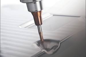
The same general practices of machine tool maintenance, fixturing and rigidity of tool setup recommended for turning apply equally well for milling. Short tool extensions and properly adjusted machine tools are essential to good performance.
To avoid chipping, several techniques can be employed. Milling a short distance at the exit side of the part before starting the cut is very effective in avoiding breakout, just as chamfering the end of a cylinder is for turning. Lowering feed-rates will lessen chipping upon exit, but directly affects productivity. Tool rotation can be used to lessen exit edge chipping for flat surfaces by using climb milling rather than conventional milling passes. Elimination of "up" milling rotation for contour milling will generally adversely affect tool life and is not recommended.
The advent of high-speed milling centers with CNC controls creates the best circumstances for use of diamond-coated end mills. Multiple fluted-coated end mills allow maximum use of the higher spindle speeds without sacrifice to wear, while unattended profiling can be used to maximize productivity results.
Always use square end mills with a small radius. Diamond tools are very brittle and sharp corners will break upon entry into a cut. A 0.010-0.015" corner will greatly strengthen the tool, providing extra durability.
Always use cutters with the most flutes possible for the machining conditions. Roughing at high feedrates usually dictates using only two flutes. Economics dictate use of four flutes because the cost for a diamond-coated end mill is the same, regardless of flute count. Improved surface finish always results from multiple flutes.
Starting conditions for milling vary considerably for graphite, but generally 2,000 spm and 0.004 inches per flute per revolution is a conservative starting point.
Drilling Graphite
Special care should be used to clear the machining dust from holes during the drilling process. Proper removal will create the opportunity to use higher spindle speeds as well as reduce the wear of the drill. There are no size limitations for drilling using diamond-coated drills as there is with HSS or carbide drills (wear) or PCD tipped drills (debonding).
As in all applications these conditions will vary according to the grade of graphite being machined and the general setup and dust removal practices.
Summary
Real economic benefits can be gained using diamond-film cutting tools, but only if applied properly. Using starting parameters that are usually much higher than carbide operating ranges is the beginning to obtaining optimum results from diamond tools. Productivity gains come from pushing the tool for peak performance, not preservation of the coating. The next segment will review considerations for machine tools and accessories used in machining graphite and some applications where the diamond tools have been a success.
Related Content
Treatment and Disposal of Used Metalworking Fluids
With greater emphasis on fluid longevity and fluid recycling, it is important to remember that water-based metalworking fluids are “consumable” and have a finite life.
Read MoreHands-on Workshop Teaches Mold Maintenance Process
Intensive workshop teaches the process of mold maintenance to help put an end to the firefighting culture of many toolrooms.
Read MoreMoldmakers Deserve a Total Production Solution
Stability, spindle speed and software are essential consideration for your moldmaking machine tool.
Read MoreThe Benefits of Hand Scraping
Accuracy and flatness are two benefits of hand scraping that help improve machine loop stiffness, workpiece surface finish and component geometry.
Read MoreRead Next
How to Use Continuing Education to Remain Competitive in Moldmaking
Continued training helps moldmakers make tooling decisions and properly use the latest cutting tool to efficiently machine high-quality molds.
Read MoreAre You a Moldmaker Considering 3D Printing? Consider the 3D Printing Workshop at NPE2024
Presentations will cover 3D printing for mold tooling, material innovation, product development, bridge production and full-scale, high-volume additive manufacturing.
Read MoreReasons to Use Fiber Lasers for Mold Cleaning
Fiber lasers offer a simplicity, speed, control and portability, minimizing mold cleaning risks.
Read More


.png;maxWidth=300;quality=90)


