How Tool Design Changes with the I.C.E. Process
Mold design will change as incremental cavity ejection is used in the molding process—which includes draft angles, finishes, undercuts, stresses, cycle time and quality.
The new product starts with a vision to make life simpler. Whether it’s an improvement upon an existing prod-uct or a new idea, it’s meant to make things better and challenge future progress.
Incremental cavity ejection (I.C.E.*) fits into this arena. Taking what we’ve learned over the years in designing molds and stepping forward with a new idea that can assist the mold designer, mold builder and processor to be more competitive in the marketplace.
How Things Have Been Done
For this article we’ll focus on single-cavity, container-based products. Typically, the mold would have an internally cooled cavity block (hot side of the mold) with a cooled gate insert. The part would be filled through a sprue bushing or with a hot tip.
On the ejector half (cold side) we would place water in such a way as to optimize cooling since we know that 70 to 80 percent of cooling will take place here. The part would be ejected by either pins or a stripper ring. A robot also could be used to remove the part from the mold.
Consideration would then be given to metals that would enhance the cooling and stand up to the wear for a stripper shutoff. Draft angles and even undercuts need to be considered before starting the design.
Interlocks are placed at the parting line on the molds. This is because the leader pins and bushings, when new, have a possible clearance of .0025". Locking the mold together in the correct position prior to injection is of extreme importance to the mold designer and molder to obtain the correct wall thickness. Interlocks come in two basic styles: straight side or 10° tapered side. The tapered type uses its 10° taper to align the two halves and, when clamped, locks very well. The straight-sided ones have a clearance of .0004 when new and engages and releases with a ¼ to ¾ parting line gap. They do not truly lock.
The above three components all wear and are lubricated to decrease the wear.
Improving on the Past
Flat surfaces on the outside of the mold should be available where indicators can be placed to measure the difference between lock up and no lock up. Hanging the mold so the tie bars of the press bring the mold together at the lock up position is up to the setup people. However the mold designer should specify a plaque on the mold stating, “flat surfaces for indicators are on the outside surfaces of this mold to indicate mold lock up and no lock up.” The less the difference, the less the cycle time, the better the part, and little to no lubrication needed on the leader pins, bushings or locks. In the regular molding process this prevents the very high forces from the core with the molded part on it applying a high force to the cavity walls, causing draglines on the outside surface of the part.
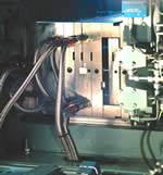
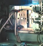
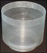
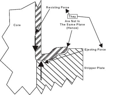
In Photos 1 and 2, one formula for the part in Photo 2 comes up with 37.44 seconds cooling time, so the 25-second total clamp time was a very good cycle with the regular process. So why was clamp closed and not reduced from 25 seconds? The molder reduced the cooling time by a few seconds and demonstrated what happens to the product (see Figure 1). The force to eject and the force resisting ejection are not in line with each other. Only sleeve ejectors pushing off a pin or pins pushing out a plastic stud are direct, but only to the pin or stud, not to the rest of the part. If the cooling time is shortened below its minimum, it will always cause distortions or additional stress.
Another Option: I.C.E. Mold Design
Using the part in Photo 2, the mold design will incorporate the I.C.E. process. In doing this we have to keep in mind that we have to please the product designer, molder, accounting and the end user. The part cannot be damaged on ejection and an improved cycle time that raises quality would be a highlight to this mold design.
Figure 1: Air Flow
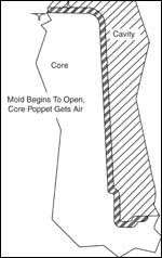
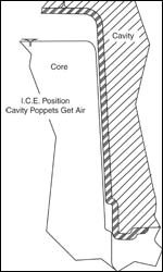
In the mold design, a shut off-style hot tip will be used in place of a cold sprue and there will be no mechanical ejector system, no stripper and no ejection plate. Air poppets—allowing easy air flow—are placed on the top of the core opposite the gate and two air poppets are placed at the bottom of the cavity toward the outer edge of the part. Air poppets on the cavity and core are controlled by three-way solenoids. The solenoid to the core poppet is turned on before the mold opens.
Figure 2: Cooling and Shrinkage
Cooling and changing dimensions go together at the same rate, when they do not, stress is introduced to the plastic part. The plastic that has been heated and melted during the injection molding process starts shrinking once it enters the gate to fill the part, but the core—being solid—does not allow the part to shrink; therefore, creating restrained shrinkage and stress.
With I.C.E., the core moves out of the cavity with almost no adhesion of friction between it and the plastic (because of the high pressure air from the poppet), the part immediately begins to relieve its restrained shrinkage by reducing its internal dimensions. It does this as it stays in loose contact with the core, so the inside of the part thickness that is in the melt stage and the material closer to the skin that has some stress, relieves itself or cools down with less stress.
Figure 3: Tension
The plastic force is now fairly high and acts more like a spring because of tension, and as the core gets out of the way the tension is relieved. When the core has moved out to the I.C.E. dimension, the solenoid to the cavity opens to the same airline with equal pressure on both sides of the part. The part immediately begins to move with the core. The mold continues to open slowly. Both solenoids dump the air pressure—the volume and pressure is leaving from the parting line on both sides of the wall thickness and it drops to near zero.
Process Comparison
In the industry standard and I.C.E. molding processes, as long as packing is going on, the heat transfer is equal to both cavity and core. Packing ensures that both walls of the part are in intimate contact with the mold. The pressure is from the machine minus the drop between it and any point along the packing path. When machine packing shuts off, the standard and the I.C.E. process become separate.
The Standard Molding Process
In the standard process, the clamp closed time must be enough for the part thickness to reduce enough for the core with the part tightly on it to come out of the cavity without hanging up on, or getting damaged by, the cavity walls. This is the major factor in setting all the temperature, pressure and times controlling the regular process and it is called cooling time.
During this time restrained force is built up in the part because the core is preventing a dimensional change, this force is exerted on the core and heat extraction goes almost exclusively to the core. Because of this, stresses will remain with the part forever (unless annealed); therefore, the tension force exerted on the core is very high and the force resisting ejection also will be high. Increasing the ejection force will definitely add more stress in different areas of the part (see Figure 1). That is reasonable draft needs to be added to the inside wall of the part.
The I.C.E. Molding Process
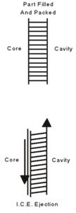
With the I.C.E. process and the mold designed with I.C.E. in mind, many parts offer little or no breakaway force from the core when high pressure air is used first to separate the now formed and packed—but far from rigid—part in intimate contact with the cavity holding it there (see Figures 2 and 3).
For the two parts shown and many more when packing is completed, the mold can begin to open. This means that cooling from both sides has been equal for the entire time the part was formed and packed in the mold.
The mold cooling design for the parts in Photos 1 and 2 was for the standard molding process and because it was taught, published and accepted that the core takes most of the heat out of the part, greater effort and cost has been put into cooling from the core and much less in the cavity.
Mold cooling with the I.C.E. process is different. For just a moment, forget conventional mold cooling for the parts in Photos 1 and 2. Think of a flat piece of plastic .120-inch thick and you want to cool it down 100° F. How much faster can you cool it using both sides equally versus only one side only?
With cooling traveling only .060 inches to a mold wall, fill and packing is the best way to cool a plastic part. The thermal conductivity through the plastic is the most important time factor in cooling parts. When I.C.E. is used, the force on the part to de-mold is small so the molder can increase the mold temperature and packing time, and accomplish more cooling in less time.
With the I.C.E. process the only causes of uneven cooling are impingement at the gate area, shear, intersecting walls and changes in wall thickness, etc. They all can be dealt with in the cooling design, which is usually easy, but sometimes not worth the cost. The mold designer must make that judgment.
How does using the I.C.E. process always lessen cycle time? The pressure applied to the plastic to eject this part in the I.C.E. process is close to zero, so the formed part can be ejected at a higher temperature than the deflection temperature. Once injection is over, the temperature near the center of the .120-inch thick wall will be above the melt temp. However, the skin of this part touching the core and the cavity is closer to the mold, so the part can be removed from the mold.
The hotter the better for the I.C.E. process because when high-pressure air enters the air poppet on the top of the core it will find its way to the parting line? The gate is frozen or shut. It is not going to blow a hole in the plastic because it’s backed up by the cavity. It can only go between the formed part and the core. As it moves its way down the core there will be no adhesion or friction remaining. So ejection off the core begins as the mold opens with air pressure forcing the formed—but far from rigid part—in intimate contact with the cavity.
Is heat extraction equal? That’s up to the air volume leaving and the pressure, and that is controllable, but anything is better than the standard process. The potential difference occurs only for the short time that it takes to open to the I.C.E. position. Once the part is out of the mold, cooling uniformly is easier, slower and less stressful to the part.
No (or Reduced) Draft Angle
With I.C.E., plastic is at a higher temperature when the mold opens. It is between two parallel walls and is somewhat like rubber. Pull on it and it stretches and gets thinner (see the lines in Figure 4). The lines represent the molded thickness .120" of the part and is held stationary on the cavity wall by air pressure and/or cavity finish when the core moves out about .040 inch. It stretches and goes diagonal and there is room for the core to move out and release from the cavity radially. It does not over-stress because of temperature.
Why will draft angles versus texture depth have to be rewritten? Because draft angles and texture depth was written for the standard process and etching. Etching can never be sharp and therefore is more forgiving. With I.C.E. the part moves away radially and does not need forgiveness.
The new formula for draft angles and texture depth is:
% (Total shrinkage of plastic)
(Dimension across part) = Texture Depth 2
A challenge! How would you design and build a mold for the part like in Photo 1 in PVC or TPR that the molder would have no trouble molding?
Summary
To produce a quality part in the standard molding process, the breakaway force to open the mold with the part on the core and to eject it off the core is the major factor in setting all the temperatures, pressures and times controlling the process. With the I.C.E. process all injection molded parts that have a cavity and core will offer less, and for many no breakaway force from the core or cavity except what is needed to hold the part to the core for final ejection or removal.
*I.C.E. has U.S. Patent # 5,932,164.
Related Content
It Starts With the Part: A Plastic Part Checklist Ensures Good Mold Design
All successful mold build projects start with examining the part to be molded to ensure it is moldable and will meet the customers' production objectives.
Read MoreTolerancing in Mold Design, Part 1: Understanding the Issues of Conventional Bilateral Tolerancing
Mold designers must understand the location, orientation and form limitations of conventional tolerancing before changing to another dimensioning system.
Read MoreThree Good Reasons to Switch from Three- to Five-Axis Machining in Moldmaking
Five-axis machining technology is a great tool in the moldmaker toolbox.
Read MoreMold Design Review: The Complete Checklist
Gerardo (Jerry) Miranda III, former global tooling manager for Oakley sunglasses, reshares his complete mold design checklist, an essential part of the product time and cost-to-market process.
Read MoreRead Next
The Key to Up-Front Mold Design
By involving the tool designer, builder and molder early in product development, you can reduce turnaround time by weeks or even months, shave weeks off the mold construction cycle and reduce costs by eliminating potential product design troubles.
Read MoreDesigning the Mold: The Foundation for Success
The impact of different mold materials with regard to cooling; how to determine waterline placement for optimum cooling; placing cooling where heat is concentrated in the part; and, how to select a mold base sized for the machine being used.
Read MoreHow to Use Continuing Education to Remain Competitive in Moldmaking
Continued training helps moldmakers make tooling decisions and properly use the latest cutting tool to efficiently machine high-quality molds.
Read More





.jpg;maxWidth=300;quality=90)

