How to Fix Family Mold Problems With Flow Simulation
Mold flow simulation is important to use when building a mold, but it also can help moldmakers solve flow problems after the mold is built.
It is well known that family molds can decrease tooling and production costs. However, family molds always will have some inherent problems. Flow simulation - when properly applied - can solve some of these problems, even after tooling has been produced. The following example demonstrates the effectiveness of flow simulation on family molds.
Exide Technologies, Inc. (Princeton, NJ) - one of the largest makers of automotive batteries worldwide - was producing a family of parts that were similar in geometry to a product they already produced. The only difference was that the new parts were approximately 15 percent larger; an increase Exide thought was negligible. During tooling production, Exide chose to bypass flow analysis because of the many similarities in the new parts and the parts they currently produced. This would prove to be a costly assumption.
Exide built its family mold using the same runner design as its smaller family mold and simply increased the size of the runners and gates. During tooling trials, one of the parts repeatedly produced short shots. When it did fill, the other part flashed badly. Also, both of the parts exhibited significant warpage.
The mold had a small part with a nominal thickness of 0.007" and a larger part with a nominal thickness of 0.015". The mold design used four drops to feed eight runners on each part. The runners and gates were all the same geometry.
Solving the Problem
Analysis of the individual parts showed that the leading cause for the high degree of warpage was the flow imbalance caused by multi-gating. Multiple gates are often recommended for long panel-type parts to decrease warpage because of material orientation effects. Eight gates proved to be excessive in this case. The excessive number of gates produced a complex material orientation, increasing residual stresses and thus resulting in warpage. The matters also were made worse by a lead (high heat capacity) insert in one of the parts that produced a heat sink - decreasing the flow front temperature at one area of the part.
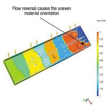
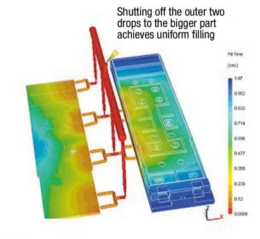
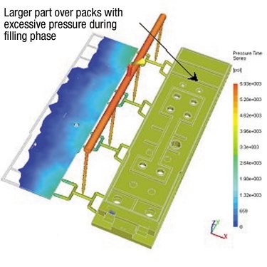
Figure 1 shows the melt contribution for the individual gates in different colors. Ideally, each of the bands should be of equal width with a straight overlap. Here it can be seen that the melt from some of the gates actually changes its flow direction, leading to an uneven material orientation. Figure 2 shows one of the analyses of the parts with the runner system. This graphic reveals a more serious problem with runner balancing. The bigger part, which had a higher nominal thickness, would fill first and over pack. Also, the clamp tonnage results shows that it had exceeded the machine limit of 300 tons. This led to severe flashing and high part weight. Further analysis with a reduced injection rate or injection pressure made the smaller part not fill out completely. These analyses showed that the oversized runners (0.25") on both of the parts diminished the "Molding Window," or the range of parameters in which the mold can successfully produce parts.
With these results in mind, one of the recommendations was to shut the two outer drops completely to the bigger part - the one that filled first (see Figure 3). This ensured that both of the parts filled almost at the same time. By filling both of the parts at the same time, the over-packing situation was avoided. This ensured that the clamp tonnage (250 tons) was under the machine limit of 300 tons. Also, the bulk stress levels on both of the parts were under the recommended value.
On any molding project, it is best to apply mold flow design principles at the earliest stage possible. This not only serves to the overall success of the project, but also eliminates expensive retooling costs. Even a very crude analysis done at an earlier stage will answer some important questions like probability of fill, cycle time, machine requirements and runner sizing, just to name a few. However, this example also demonstrates that an effective application of mold flow simulations as a troubleshooting tool at the production stage also will produce useful knowledge and solutions.
Related Content
How to Manage Wall Thickness Changes in Your Mold Design
To ensure even filling and cooling, consider wall section transitions, corners and fillets, ribs and bosses, lip and rim designs and CAE flow simulation software.
Read MoreHow to Analyze and Optimize Cutting Conditions to Reduce Cycle Time
Plastic injection mold design and manufacturing company puts NC program optimization software module to the test. The results were surprising.
Read MoreIt Starts With the Part: A Plastic Part Checklist Ensures Good Mold Design
All successful mold build projects start with examining the part to be molded to ensure it is moldable and will meet the customers' production objectives.
Read MoreWhat Is Scientific Maintenance? Part 1
Part one of this three-part series explains how to create a scientific maintenance plan based on a toolroom’s current data collection and usage.
Read MoreRead Next
Reasons to Use Fiber Lasers for Mold Cleaning
Fiber lasers offer a simplicity, speed, control and portability, minimizing mold cleaning risks.
Read MoreHow to Use Strategic Planning Tools, Data to Manage the Human Side of Business
Q&A with Marion Wells, MMT EAB member and founder of Human Asset Management.
Read MoreAre You a Moldmaker Considering 3D Printing? Consider the 3D Printing Workshop at NPE2024
Presentations will cover 3D printing for mold tooling, material innovation, product development, bridge production and full-scale, high-volume additive manufacturing.
Read More




.jpg;maxWidth=300;quality=90)


