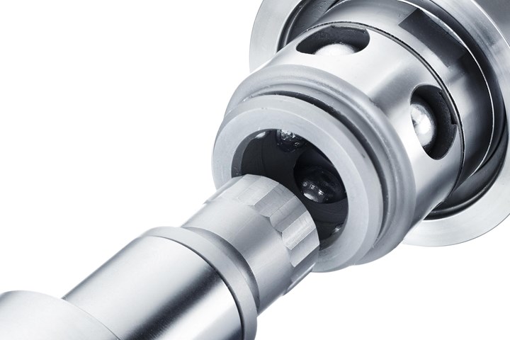
Compact round latch lock units define movement and latching with collision protection. Photo Credit: Hasco America Inc.
Here is a look and functions of internal and side-mounting latch-lock devices that help to reduce mold build times and increase safety:
1. The latch pull rod and housing of an internally-mounted latch lock system allows the actuation of the split lines in sequence without using springs. For example, a second parting line remains closed while the first parting line is activated. Once the first opening is achieved, the pulled plate locks and the second parting line activates to strip or eject the part.
2. Internal latch lock systems with a small footprint allow use in designs without adding to the mold base’s overall length by width while also activating multiple mold parting line openings.
3. Internal latch lock systems with floating plates that do not require further plate locking, allow molds to actuate multiple split openings fast and accurately.
4. The following sequence is recommended for a pulling system: Both plates (or sets of plates) move forward, the latch lock unlocks, the rear plate stops and the front plate moves the rest of the stroke. This sequence allows the front plate to strip or eject parts on final movement while the plate or plates are not locked in place.
5. The following sequence is recommended for a pushing system: Both plates (or sets of plates) move forward, the rear plate or plates unlock, the front plate stays in place as the rear plate moves forward, and the plates do not lock in position.
6. Designs using central multipoint locking roller balls around the circumference of an internal latch lock system in fast-running molds, align the mold with any offsets due to misalignment by thermal expansion.
Latch sizing considerations include mold size, required stripping forces, opening and closing requirements in the press and actual required strokes.
7. Rolling steel balls (not rollers or springs directly at the latch locking actuation location) achieve low-wear stroke guidance on stroke movement at the plate opening using a free gap principle.
8. Integrated collision protection keeps reaction forces from impacting the latch lock. The rear of the latch lock has an internal spring design that cushions the center actuation sleeve moving around the control pin. The steel roller balls run along the outer diameter of the center actuation sleeve, allowing the center sleeve to move freely and with speed.
9. A compact design eases the installation of complex plate movement within the mold base, resulting in safer mold transport and storage and more space for other necessary components.
10. Latch sizing considerations include mold size, required stripping forces, opening and closing requirements in the press and actual required strokes.
Related Content
-
The Ins and Outs of Hot Runner Temperature Control
A training checklist that explains the why and how of proper hot runner temperature control and system management.
-
6 Ways to Optimize High-Feed Milling
High-feed milling can significantly outweigh potential reliability challenges. Consider these six strategies in order to make high-feed milling successful for your business.
-
The Benefits of Hand Scraping
Accuracy and flatness are two benefits of hand scraping that help improve machine loop stiffness, workpiece surface finish and component geometry.


.jpg;maxWidth=300;quality=90)


