Direct Metal Laser Sintering and Tooling
The applications, benefits and limitations of direct metal laser sintering for mold manufacture.
Direct metal laser sintering1 (DMLS) is a revolutionary technology that is beginning to gain recognition in North America. Better known in Europe, this technology has enabled many companies to dramatically reduce their time-to-market for rapid tooling and direct metal applications.
DMLS is an additive technology that works by sintering very fine layers of metal powders layer-by-layer from the bottom up until the build is complete. The process begins by sintering a first layer of 20-micron powder onto a steel platform. The platform then lowers by 20 microns, a fresh layer of powder is swept over the previously sintered layer, and the next layer is sintered on top of the previously built one. A powerful 200W Yb-fibre laser is precisely controlled in the X and Y coordinates—allowing for exceptional tolerances to be held (+/-0.001"/inch).
The latest technology takes advantage of a dual spot laser allowing feature sizes as small as 0.203mm (0.008") to be built. With a machine build envelope of 250 x 250 x 215mm, many medium to small parts and inserts can be constructed in hours and days versus days and weeks using traditional processes.
Once started, the machine builds unattended, 24 hours a day. Parts and inserts that come out of the machine typically will go through a series of post steps including support removal, shot peening, etc. The parts coming out of the machine are 100 percent sintered and require no post-sintering or other infiltration process.
Applications
DMLS was originally developed to create complex cores and cavities and other geometries for the tooling industry. The initial machines and materials were quite enhancing compared with other additive fabrication technologies on the market at that time; however, the technology was not the equal to more traditional methodologies such as CNC machining and sinker EDM. Newer machines and continued material developments have propelled DMLS into being a dynamic and viable technology for many rapid tooling and series part production applications.
The process generally begins with a designer or engineer going through a selection process for how the tool will be constructed. A myriad of factors come into play, such as leadtime, tool complexity, tolerances required, materials to be shot, and other criteria—many of which are factors that get considered with any decision-making process involving traditional tooling decisions. Once the designer has designated DMLS to be a viable route to take, a 3-D CAD model of the components (core, cavity, etc.) need to be constructed.
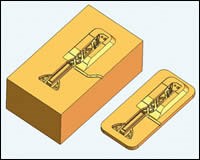
It is important to take into account that designing the optimal tool for the DMLS process is very different than designing the same tool for more traditional methods. Volume and height of the inserts or components should be minimized as these tend to be time and cost drivers (see Figure 1).
Once a 3-D CAD model has been developed, an .stl file is exported to the DMLS build software. Build parameters are checked and the build is initiated in the machine. Once completed, the build platform with the tooling inserts or components are removed from the steel platform and post operations, such as polishing and other traditional tooling steps, are performed on the components before they are mated up with other tooling items.
Various materials are available to run in the DMLS technology, including bronze-based alloy, low-carbon steel-based alloy, tool steel-based alloy2, 17-4 PH stainless and cobalt chromium. Material research is continuous and new alloys, such as Titanium and Inconel 718, are in the process of being developed along with many other alloys.
Generally speaking, DMLS is an appropriate technology to use when the components being considered are both smaller in size (fitting inside the build envelop) and tend to have complexity associated with them that would otherwise be costly and time-consuming to produce using more traditional methods, such as high-speed CNC machining, plunge-style EDM, etc.
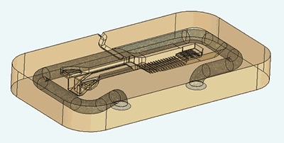
There are a few advantages of the DMLS process (see Figure 2) over more traditional methods, including:
- The ability to create multiple parts at the same time in one build
- Operation of the machine unattended 24 hours a day
- Ability to create internal sharp corners and other complex geometry that otherwise would need to have an EDM operation
- The ability to create conformal cooling lines in the tool
Despite these powerful advantages, the DMLS technology is but another tool that should be considered when evaluating tooling options. The size limitations of the build envelope would prevent this technology from being used for medium or larger molds. Also, the technology is most appropriately used to build the complex components of a tool while leaving the easily machined components for more traditional technologies.
Case Study
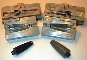
An example of a combined approach was a tool that was required for a short leadtime project related to an automotive component. The item requested was a shifting knob that required two tools, one to produce the core of the part to be shot in Celcon, and a second tool that would overmold the Celcon part with an 80A durometer PVC material.
The core part was an ideal candidate for the DMLS process due to the features and part size. With an overall length of 3.25" and a maximum diameter of 1.25”, the tooling core and cavity were able to fit on the DMLS platform together in one build.
In addition, the ribs that were an integral part of this item were an ideal fit for the DMLS process due to the technology’s ability to create the ribs directly in the tool. In this particular case, traditional methods would have required sinker EDM work that would have made the tool more costly and taken longer to produce.
Using the DirectMetal 20 material, both inserts were able to be grown in the DMLS process within 48 hours, and because the machine runs unattended, this meant these components of the tool were able to be processed within two days after completion of the tooling design. Once out of the DMLS machine, the core and cavity were cut out of the build platform and a few secondary operations were performed including drilling the cooling lines and dusting off the parting line of the tool.
Concurrent to these DMLS components being built, the more straightforward parts of the tool were being produced via traditional CNC machining methods, including lathe cutting the core pins and machining the second tool that had a geometry well suited to CNC milling. For these components, P20 steel was selected.
Upon completion of the various tooling components both in DMLS and CNC, simple hand polishing was performed to an NTMA #190 spec. Total time to design and construct the two tools was three weeks and parts were shot in the fourth week in various colors as dictated by the client. The total cost for both tools was just under $13,000.00 (see Figure 3).
Summary
Direct metal laser sintering is quickly gaining recognition as perhaps one of the most enhancing technologies available in the additive fabrication arena today. Recent material developments coupled with phenomenal detail resolution and speed of fabrication are making DMLS inserts and components a very powerful tool that can be used to shorten tooling leadtimes, reduce costs and push more projects through in the same amount of time. Recent machine enhancements coupled with tremendous advancements in new materials have allowed DMLS to be a technology to consider not just for rapid tooling requirements, but also for production tools and non-traditional applications such as die cast tools.
References
- EOS GmbH (Electro Optical Systems), located in Munich, Germany, developed the technology and manufactures the machines and materials in support of the DMLS market.
- DirectMetal 20 (bronze-based alloy), DirectSteel 20 (low-carbon steel-based alloy), DirectSteel H20 (tool steel-based alloy), 17-4 PH Stainless and Cobalt Chromium.
Related Content
6 Ways to Optimize High-Feed Milling
High-feed milling can significantly outweigh potential reliability challenges. Consider these six strategies in order to make high-feed milling successful for your business.
Read MoreMoldmakers Deserve a Total Production Solution
Stability, spindle speed and software are essential consideration for your moldmaking machine tool.
Read MoreThe Benefits of Hand Scraping
Accuracy and flatness are two benefits of hand scraping that help improve machine loop stiffness, workpiece surface finish and component geometry.
Read MoreMachining Center Spindles: What You Need to Know
Why and how to research spindle technology before purchasing a machining center.
Read MoreRead Next
Integrating Rapid Prototyping With the Shop Floor
The CNC-based RP process works to complement existing production techniques.
Read MoreRapid Tooling Via Stereolithography Gets a Closer Look
Industry roundtable reports initial findings.
Read MoreGrowth Strategies for the U.S. Moldmaker - Understanding Your Competition - Here and Abroad
This article begins a four part series that will describe the current competitive conditions in the plastics tooling industry and what some companies are doing to grow their businesses amidst challenging conditions.
Read More




.jpg;maxWidth=300;quality=90)
