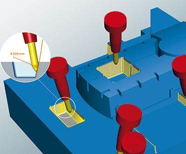
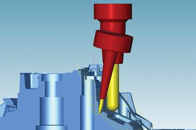
 In a virtual machining center environment, individual part programs can be linked with smooth and safe connections that enable the cutter to remain close to the workpiece. Source | Open Mind Technologies USA Inc.
Have you ever read articles or attended presentations where an opening statement indicates that interactions of machine tools, software and tooling dictate the success of a manufacturing process? In these cases, what specific information has followed to substantiate the well-worn thesis? This article intends to go beyond general statements and identify specific items where CAM software can take advantage of machine tool capabilities to benefit the user.
How Well Does Your CAM System Know Your Postprocessor?
Many CAM software products produce toolpath process data and neutral-formatted output files, such as APT CL data. An external postprocessor program then translates the neutral data to a specific machine tool focusing on machine tool kinematics and controller syntax information. This traditional process has certainly been successfully applied.
However, the disconnect between toolpath planning and postprocessing means that the postprocessor cannot access certain information to leverage the machine’s capabilities. Likewise, the CAM program often is separated from the details of the destination machine tool. The benefit of an integrated postprocessor technology is more dramatic in multi-axis applications.

A comparison of a new generation of programming assistance and analysis (left) and traditional programming assistance/analysis methods (right) reveals key differences such as distinct points near geometry features and even spacing in open areas.
Description of Local Programming Coordinate System
One example of additional information that can be passed from CAM to postprocessor to help machine performance is a description of the local programming coordinate system. Many CAM software calculations operate on simple geometry on arbitrary orientations (such as holes, pockets and engraved lettering) by defining a local coordinate system or frame and programming occurs in this orientation.
The postprocessor makes necessary adjustments so the postprocessed machining instructions are transformed relative to a defined part origin and reference on the machine tool. Does your postprocessor know both the part setup coordinate system (NCS) and the local programming coordinate system (frame)? For many machine controllers, this information can be used to enable 2-D style programming with canned cycles and cutter compensation to be used for many operations occurring on tilted work planes.
Functionality Regarding Connections or Linking of Multi-Axis Drill Patterns
In another example, the CAM software has functionality regarding connections or linking of multi-axis drill holes. If the CAM software knows that the machine tool control has tool center point management capability, a smooth linking path can be applied close to the workpiece, compared to typical retracts to pre-defined safety planes. The benefit is a non-collision tool path while avoiding unnecessary cycle time caused by continually moving to safety zones. By having this information available, there is higher process assurance and machine tool performance.
Modern CAM software simulators that are connected to CAM software and aware of the machine tool, controller and part model and can also provide the linking moves automatically, without effort by the CAM programmer. This can apply to all tool path types with the same cutter, not only for linking between holes.
CAM software systems can positively impact the performance of downstream processes in the machine tool and controller by knowing these systems and having mechanisms to model and coexist with the capabilities of these process steps.
How Well Does Your CAM System Know Your Machine Tool?
Machine tools have different capabilities due to size, speed, power, application intent and other constraints and limitations. It is helpful for a CAM software system to have strategies that can enable the machine to use these features. One end-user may have equipment to produce large molds and smaller, high-speed machines to produce inserts or electrodes. So, milling machines with significantly different capabilities may even reside within one shop.
Many shops today cover a wide range of processes or applications. A large mold shop may have heavy-duty roughing machines, more dynamic finishers and specialty gun drills. Also, to balance workload through business cycles, many shops have extended their business beyond mold and die, to include aerospace or medical applications. The CAM software should handle multiple processes and materials.
Five-Axis Machining
Some of the clearly differentiating characteristics of machine tools are found in the class of five-axis machines. There are obvious distinctions, such as the kinematic layout—whether the rotary axes are with the cutter or the part or mixed; how the rotary axes are designed into the machine, and whether the axes are orthogonal to each other or at other angles.
Much is said and written about five-axis machining. This is a powerful machining concept with well-documented benefits to improve tooling, setups, surface finish and to enable access to complex geometries. However, the complex dynamics of moving heavy masses (machine and part) suggest that full five-axis simultaneous solutions are not ideally suited for every application.
4+1 Machining
In many mold and die applications, users can get the tooling and setup benefits of multi-axis machining by seeking solutions with a locked pivot axis and active use of the rotary axis. This process is called 4+1 machining. In addition to facilitating improved dynamics, this process also takes advantage of the typically higher-performing rotary (C) axis on a machine tool. However, in some cases, the workpiece has large mass and active use of the rotary axis is not preferred.
Mold components often have product features with small radii that produce corners and edges on finished components. Historically, these features have been made with an additional EDM process operation. With five-axis machine tool technology, more such features are machined today. However, small cutter diameters required to produce these features may be ineffective with long cutter stick-out lengths. The process performance improves for small cutter diameters with short cutter lengths and tapered thick shafts. A five-axis machine is generally used to accommodate thick-shaft tooling requirements, by orienting the cutter in a direction with open space.
3+2 Approach
The cutter and machining performance is still improved by limiting the number of active axes. A process called multi-axis indexing is well-suited for heavy roughing cuts. It seeks to simplify five-axis programs into segments of 3+2 machining, thereby further simplifying machine dynamics and increasing cutter stability. Multi-axis indexing provides a process variation to enable the machine to manage multiple segments from one programming job and re-orient between them. To improve the efficiency of the indexing tool paths, the tool paths are trimmed against the remaining stock to minimize moves in the air.
In some applications, such as bumping the cutter up and down along the walls of a complex core or cavity, each individual toolpath stroke may have a unique 3+2 solution and a five-axis reorientation occurs while the cutter is transitioning between strokes. The process can, therefore, cut an entire hard milling core or cavity with fixed-angle machining in one program.
The machine tool performance is improved by using its multi-axis capability judiciously, yet applying the proven 3+2 process to ensure a high-quality surface finish and longer cutter life.
Five-axis machining is a widely used process, and it is easier with a software system designed to attain five-axis performance.
How Well Does Your CAM Know Your CNC Control?
Modern control systems include the ability to look ahead at coming NC blocks and offer smoothing functions. While these functions provide a strong safety net and can improve surface finish, a better result is achieved when the CAM software takes greater care about point spacing and precision of the NC points to the model surface and ensures the NC points and tool orientations are intrinsically smooth. Higher-quality CAM data will be processed more easily through the CNC control smoothing.
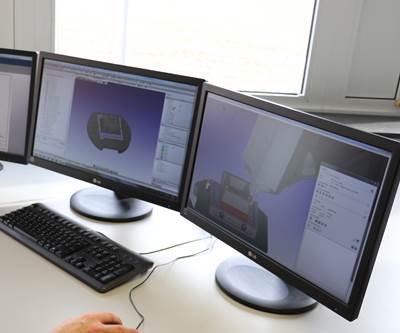
Also, if the CAM system can accurately model the machine by a digital twin concept and control functions about tooling and offsets, then the CAM software simulation can confirm tool paths staying within axis limits and reduce risks at the machine tool.

A new generation of programming assistance and analysis simplifies various programming tasks and identifies possible sources of error such as calculating the optimum point distribution based on part topology data and automatically creating cover surfaces for holes.
Summary
CAM software systems can positively impact the performance of downstream processes in the machine tool and controller by knowing these systems and having mechanisms to model and coexist with the capabilities of these process steps. Five-axis machining is a widely used process, and it is easier with a software system designed to attain five-axis performance.
Related Content
The In's and Out's of Ballbar Calibration
This machine tool diagnostic device allows the detection of errors noticeable only while machine tools are in motion.
Read MoreMachining Center Spindles: What You Need to Know
Why and how to research spindle technology before purchasing a machining center.
Read MoreMoldmakers Deserve a Total Production Solution
Stability, spindle speed and software are essential consideration for your moldmaking machine tool.
Read MoreThree Good Reasons to Switch from Three- to Five-Axis Machining in Moldmaking
Five-axis machining technology is a great tool in the moldmaker toolbox.
Read MoreRead Next
Broadening CAM Applications for Barrel Cutters
This alternative cutting tool geometry, along with the right CAM software, can help moldmakers reduce finish-machining times.
Read MoreHow to Implement Five-Axis Mold Machining for Higher Productivity, Versatility
Understanding the basics of five-axis capabilities justifies the investment, but exploring all the multi-axis machine benefits and approaches enhances the return on investment.
Read MoreReducing Risk to Implement CAM Software Successfully
Following a training and implementation period, new software technology can provide a strong return to the business and be key to long-term success.
Read More



.jpg;maxWidth=300;quality=90)


