The Designer’s Edge: Hydraulic-Driven Slides
Randy discusses a few challenges and solutions when using hydraulics with slides.

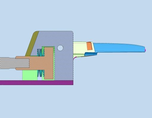
This detail shows a device that allows the cylinder to stroke all the way forward with the slide short of home position, allowing the slide lock angle on the stationary half to drive the slide home.
Hydraulics are used with slides that require excessive travel, and the standard mechanical horn pin cannot provide it. Slides can be locked in place against plastics pressure with the stationary half of a lock angle when hydraulic pressure is not needed to withhold cavity pressure. In these cases, refer to my blog on proper set/pull pressures to reduce failures.
An area of concern with hydraulic-driven slides is low draft shut-offs between the slide and stationary half. This can contribute to gulling on the shut-off as the slide is locked forward with hydraulic pressure. When adequate draft cannot be added, there is a simple method for protecting your component on the set position, if there is a lock angle on the stationary half of the mold that locks your component forward. If you use a T-slot coupler, you can create extra travel in the machined slot and add a spring to hold it in the back position. Typically, I set it up so the component is 0.030 to 0.060 from the home position when the cylinder is bottomed out. When the mold closes, the lock angle on the stationary half pushes it in the home position and collapses the spring. This protects the shut-offs from gulling. This also works when the component has critical shut-offs on the moving half that uses set speeds and pressures for protection.
When hydraulics are used on a tool, chances are good that the tool will have a costly crash condition, if this occurs. Also, when using multiple core/hydraulic sequences this situation can be a risk. In this instance, label and/or color code them. Or better yet, use different size fittings for each sequence to prevent improper setup in the press. Using male and female connections for set and pull can help distinguish them at setup. Lastly, to assist with machine setup, have a core sequence plaque on the mold that displays the sequence of the cores.


