
Collaborative Hot Runner Design to Improve Mold Performance
Improving injection mold performance requires understanding hot runner needs and options.
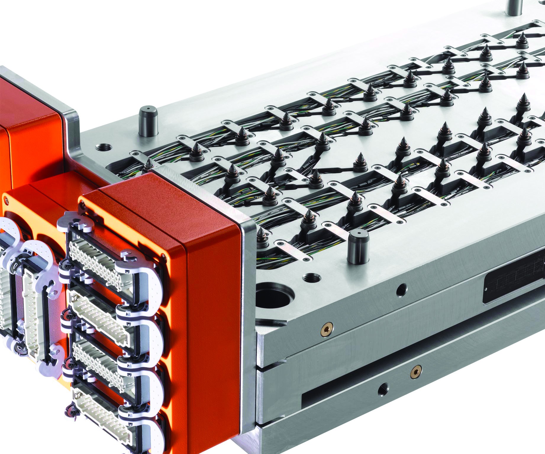
Understanding part weight, plastic material, number of cavities, nozzle style, gating style, mold size and mold material requirements helps one determine whether a standard or a customized hot runner solution is the right option. Image courtesy of Hasco.
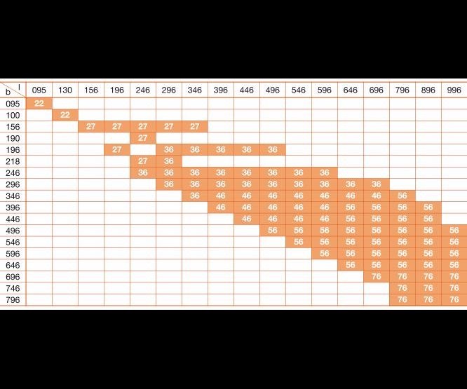
Table 1. When using hot runner systems, refer to this chart to determine which minimum plate thickness (in millimeters) for the top clamping plate is appropriate for the varying sizes of metric mold bases. Image courtesy of Hasco.
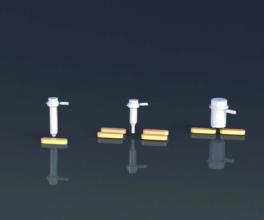
Figure 1. Hot runner nozzles can be used alone to supply one cavity (left), used alone to supply multiple cavities (middle) or used as multi gates on one nozzle to supply a single cavity or two or more cavities (right). Image courtesy of Hasco.
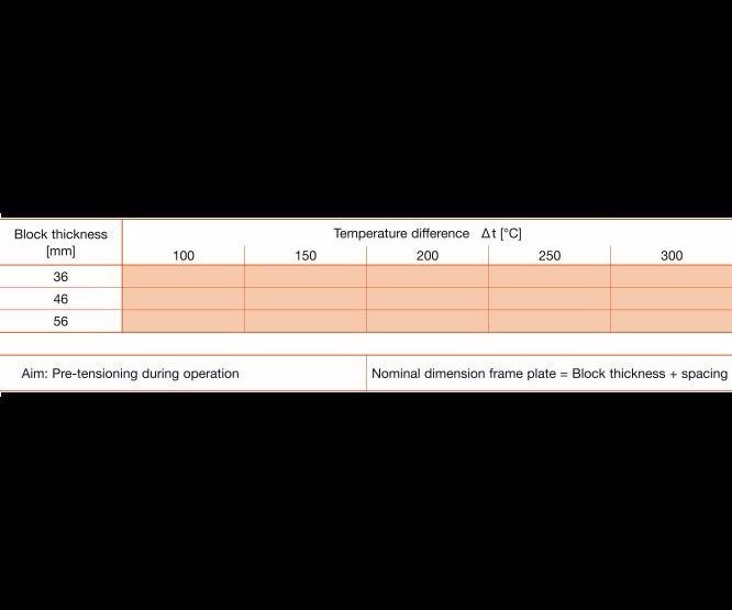
Table 2. This chart offers guide values in metric units for pre-tensioning a hot runner system. Special cases require adjustments for which the application engineer must determine the values. Image courtesy of Hasco.
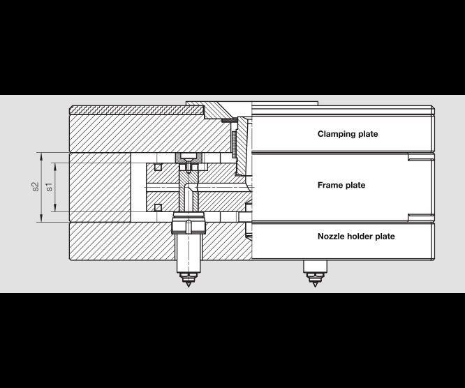
Figure 2. The right amount of pre-tensioning force is required to properly seal a hot runner system. Align the height of the installation space (see s2) according to the height difference between s2 and the s1 and the manifold plate thickness number from Table 2 to obtain a sufficient pre-tensioning force and eliminate leaking during production. Image courtesy of Hasco.


Creating the most effective hot runner system design that includes manifolds, nozzles and full hot-halves demands a collaborative approach among the moldmaking supply chain: mold builders, molders, original equipment manufacturers and technology suppliers. The first step is reviewing and understanding the vital information that the hot runner manufacturer needs to quote and build the appropriate hot runner system. Those details include part weight, plastic material, number of cavities, nozzle style, gating style, mold size and mold material requirements. Only then can a standard or customized solution be identified with the proper design process as the right hot runner solution.
Additionally, these key hot runner selection criteria can help hot runner system suppliers decide between a standard and a custom hot runner solution:


Part weight. Calculate the part weight in grams for a single molded part by multiplying the specific gravity (g/cm3) of the plastic material by its volume (cm3). This data is available within the 2D drawing or 3D data of the molded part.
Part weight in volume will help determine the proper melt flow channel sizing within the system. Your supplier will calculate this information and use it to correctly build your manifold supply channels and system.
Plastic material. Obtain data sheets and design information on the plastic material that will be processed from your material supplier/manufacturer. If this is not available, or if you are only in the quoting stage, then you can access several plastic material resources online for similar data. For example, see the Plastics Technology Universal Selector.
The required data should include the plastic material’s specific gravity in g/cm3, melt volume flow rate in g/10 minutes and molding shrinkage in percentage. The mold builder needs mold temperature in °C while the hot runner manufacturer needs to verify melt processing temperature in °C versus the mold temperature. Some data sheets omit data and/or go further into the mechanical properties of the material. For example, the data sheets may include properties like ABS (acrylonitrile butadiene styrene) specific gravity = 1.2 g/ cm3, melt flow rate = 8 cm3/10 minutes, shrinkage = 0.1 to 0.4 percent, and Nylon 66 PA (Polyamide Nylon 66) specific gravity = 1.44 g/ cm3, melt flow rate = N/A, shrinkage in flow direction = 0.007 cm/cm and shrinkage in transverse of flow direction = 0.010 cm/cm.
Cavities. Address the number of cavities next. The customer provides this data based on the required production level, which dictates the number of molded parts and nozzles. Hot runner manufacturers may recommend ways to reduce the number of nozzles per cavity or cavities, decreasing mold design and component cost and assembly size—for example, a single cavity with a single hot runner nozzle to multiple cavities on a single hot runner nozzle or multiple cavities with multiple hot runner nozzles (see Figure 1). This is the area where your hot runner supplier can work with you directly to keep your project in or under budget while still producing valid molded parts.
When considering nozzle size, note that most molded parts less than 1 gram require specially-sized nozzles, while standard nozzle systems work most effectively with molded parts that are more than 1 gram in size.
Nozzle style. Evaluate proper nozzle options. Hot runner nozzles can be used alone, as in mono shot nozzles, or they can be assembled with a standardized manifold system to supply many hot runner nozzles at once. A mono shot nozzle is a single hot nozzle that moves melt directly from the molding machine supply nozzle through to the cavity.
Determine how the nozzles will gate into or supply the molded part or parts in the system assembly. With direct gating, each cavity will have a single nozzle. For example, an eight-cavity mold will use eight nozzles. When multiple gating into a cold runner, a single nozzle will supply many cavities. When direct multiple gating, a single nozzle will supply many gates in one cavity or a single nozzle will supply many cavities.
Gating style. Determine the gate style that the molded part requires. Your customer’s molded part requirements or the plastic material that is molded generally define the gate style. For example, some materials work better with valve gates at larger diameters because of the material shear rate and stringing, while other materials work better without valve gates.
Gate styles include pinpoint clean that shows on the part but is not raised; protruding pinpoint that shows on the part and is raised; and smooth and sprue gate point with or without circular gate markings that shows a circular mark on the molded part. The gate point will determine which nozzle tip to use on the nozzle body assembly and what mark, if any, the hot runner system will make at the gating point on the molded part.
Mold size. Calculate mold size. The mold builder will create a preliminary mold layout that shows cavity spacing and factors in the overall thickness of the stack-up plates that are required in the final mold base assembly. This helps to determine the appropriate mold base size (length, width and height), and in turn, determines whether a standard metric mold base size, as shown in Table 1, or a custom mold base size is required.
Remember also to include sufficient space for insulation around the manifold, the cable channels required for the nozzles and the block-heating units, and the control connection plug wiring slots.
Mold material. Choose proper steel types for manifolds and mold plates. Toolox 33, 1.2312 or #2 holder block steel are routinely used for general-purpose plastic materials. Stainless steel types like 1.2085, 1.2099 or #7 are commonly used for corrosive or high-wear plastic materials.
The Standard Approach
If the project is deemed a “fit” for a standardized hot runner system after assessing the aforementioned criteria, then the hot runner supplier or builder works directly with the mold builder and supplies all the necessary design guidelines and system drawings.
System guidelines include the installation space, pre-tensioning (contact sealing pressure), plate thickness, mold layout, screw locations, alignment pin locations and mold temperature control circuits. Here is a sample rundown of those guidelines:
Installation space. Determine the installation space required for the hot runner manifold by considering the size of the hot runner manifold and the insulation gaps around it. The air gap serves as insulation and should be 15-millimeters-wide. The manifold must also be installed in a space that is enclosed all round to retain heat.
The height of the hot runner manifold and the spacer discs that are screwed onto it determine the installation height. The spacer discs are used to create the insulation gap. The standard gap height is either 5 millimeters or 10 millimeters on each side (top or bottom) of the manifold based on the thickness of the standard spacer discs. The spacer discs allow less steel contact between mold plates and the manifold block, reducing the loss of wicking heat. When coordinating the installation height, pay attention to the thermal expansion calculation (see the pre-tensioning section of this article) to ensure the proper assembly pre-tension sealing.
Pre-tensioning. Obtain a sufficient pre-tensioning force and eliminate leaking during production by aligning the height of the installation space (see s2 in Figure 2) according to the way that s2 compares with s1 and the corresponding number from Table 2. The thermal expansion calculation is simply the temperature difference between the manifold block and the hot runner mold frame plates. For example, a manifold is heated to 260°C and the mold plates are at 60°C, so the temperature difference is 200°C.
The tolerance for dimension s2 in Figure 2 is a function of the height of the manifold block (s1) and the temperature difference between the manifold block and the injection mold. The value is easily obtainable from Table 2.
Note that not all system assemblies rely on steel’s heat expansion as it is explained here. Instead they use additional parts, such as metal seals or screwed-in parts, to achieve the seal during production.
Plate thickness. Consider plate material during hot runner design, as the pre-tensioning required to seal the system causes very high compressive forces in the region of the spacer discs. Use pre-hardened tool steels with a strength of at least 900N/mm² for the plate to maintain a sustainable pre-tensioning force.
Use the minimum plate thicknesses prescribed in Table 1 to ensure a strong clamping plate for the mold sizes in question (b = width and l = length of mold base size). Each orange block shows the recommended thickness for that size metric mold base.
Use a three-plate stack-up when it comes to plates for hot runner system installation, which includes a clamping plate, frame plate and nozzle holder plate (see Figure 2). This configuration eases any required machining or maintenance work.
Mold Layout. Ensure that sufficient space is available for the cable channels that are required for the nozzles and the block heating units when selecting mold size. Provide allowance for the space required for connection plugs. Generously dimension the mold, or there may be space and assembly problems.
Screw locations. Use additional assembly screw connections, on top of the four, standard metric mold base assembly screw connections, to prevent any plate deflection. Employ at least one additional screw connection for each nozzle that is used to obtain sufficient mold stability. With large mold sizes, even more screw connections might be necessary. High forces are introduced into the mold because of the pre-tensioning that is generated to seal the system.
Alignment pin locations. Place alignment pins between the hot half and the cold half of the mold assembly. Properly aligned pins enable easier installation of the hot half onto the cold half for proper nozzle alignment with the corresponding cavity detail. It also eases the removal of the hot half from the mold and promotes safe placement onto a workbench. This protects any protruding nozzles as long as the alignment pins are slightly longer than the length of the protruding nozzles.
Valve gate layout. Request a clamping plate thickness that can house the required height for the cylinders and other parts used to incorporate the needle actuation height when using a valve gate system. Then determine the installation dimensions and minimum plate thicknesses for each valve gate when all required parts, like cylinders, needle guides, valve pin holders and stroke travel length, are identified.
Next, align the needle and gate geometry according to the application. Some assemblies, for instance, require hydraulic valves, while others use pneumatic or electric valves. The range of valve gate options varies the final mold plate height thickness, which is added to the manifold frame plate, the third plate and the nozzle holder plate to form the hot half assembly.
Be sure to determine the height for the third plate yourself when using a nozzle holder plate, as there is some flexibility in design with this option. However, be sure to consider the countersunk nozzle head, the inclusion of cable channels, the separate cooling channels and the rigidity of the nozzle holder plate as well.
Mold temperature. Ensure adequate mold temperature control to achieve an even temperature pattern and high process reliability. Separate temperature control circuits should control the temperature of each plate that contacts the hot runner manifold. Mold temperature plays a key role in regulating the pre-tensioning, since a defined temperature difference is required between the hot runner manifold and the mold frame plates to reliably seal the system.
Use thermal insulating sheets between the mold and the molding machine plate to prevent any additional heat from dissipating through the machine clamping plate. Also, it is important to consider the mold temperature data that the plastics manufacturer supplies when configuring the hot runner system. Adhering to these temperatures will yield trouble-free functioning of the hot runner system.
About the Contributor
Brenda Clark
Brenda Clark is an engineering manager for Hasco America Inc.


Related Content

Laser Welding Versus Micro Welding
The latest battle in finely detailed restoration/repair of mold materials.
Read More
How to Eliminate Chatter
Here are techniques commonly used to combat chatter and guidelines to establish a foundation for optimizing the moldmaking process.
Read More
Moldmakers Deserve a Total Production Solution
Stability, spindle speed and software are essential consideration for your moldmaking machine tool.
Read More
Fundamentals of Designing the Optimal Cooling System
The right mold components can help improve mold cooling and thereby produce higher-quality parts.
Read MoreRead Next

Special Coverage: Hot Runner Technology
MoldMaking Technology provides special coverage of hot runner technology as a supplement to the October 2017 magazine. Read the entire supplement here, or check out the supplement page to read each article individually.
Read More
Are You a Moldmaker Considering 3D Printing? Consider the 3D Printing Workshop at NPE2024
Presentations will cover 3D printing for mold tooling, material innovation, product development, bridge production and full-scale, high-volume additive manufacturing.
Read More
How to Use Continuing Education to Remain Competitive in Moldmaking
Continued training helps moldmakers make tooling decisions and properly use the latest cutting tool to efficiently machine high-quality molds.
Read More