
Share
Read Next


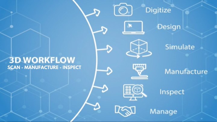
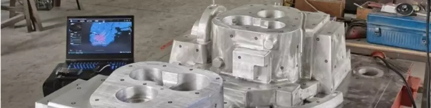
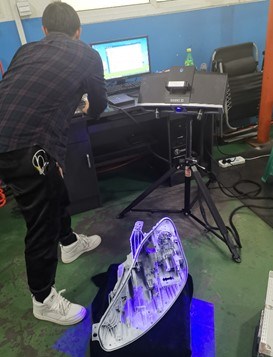
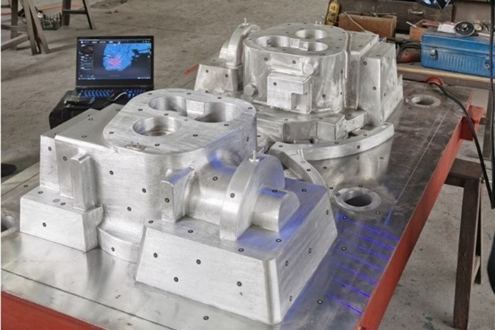
The digital manufacturing and inspection workflow. Photo Credit: Shining 3D
With the proportion of free-form surfaces increasing and the precision requirements for mold processing rising, manufacturing molds of high quality and securing the stability and quality during production has become vital. 3D scanning technologies are a game changer in these processes.
Mold Design with 3D Scanning and Reverse Engineering
Reverse engineering aims to reproduce an existing object as accurately as possible and open up mass customization and product design opportunities, especially in moldmaking. First, let’s look at how to generate CAD data for the mold using a 3D scan.


The first step of digitization in molding is 3D scanning the part. 3D data can be easily captured on site, and users benefit from swift run times, low cost, efficient handling and easy communication. The second step is processing the 3D scan data into CAD data by converting the point cloud generated in the 3D scan into CAD/CAM-capable data. The processing of the STL data produced by the 3D scanner is then reconstructed in CAD.
The part’s characteristics can be recognized based on the scan points, and these points can be replaced with CAD-capable surfaces. This process is called surface reconstruction. With the finished data of the CAD/CAM solid model, the mold build can start.
Mold Measuring with 3D Inspection
Traditional mold measuring methods are generally done manually using contact measuring tools such as vernier measuring tools or micrometers. A few attributes, such as mold width, height and depth, can be measured, while the surfaces’ curvature and concave surfaces are challenging to measure. These measuring methods can be complicated and time-consuming and make it challenging to ensure large mold measurements’ quality and accuracy.
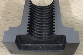
Blue light 3D scanning technology can inspect the dimensions of this mold for a nut casting and ensure accurate mold maintenance.
So, noncontact 3D scanner measurement is gradually becoming one of the primary mold inspection and measurement methods. There is a wide array of 3D inspection tools powered by different scanning technologies. For example, blue light 3D scanning. This process precisely captures small and filigree details of small- to medium-sized objects rigidly requiring persistent performance in their product lifecycle.
Blue light 3D scanning technology can help significantly to inspect the dimensions of a nut assembly and ensure accurate mold maintenance. Measurement requirements include key dimensions according to the drawing. The pitch directly affects whether the bolt and nut will fit together. The half-angle (15 degree angle) of the threaded crescent will affect the fit of the nut and bolt tooth pattern, and the consistency of the flatness of the tooth profile affects the degree of surface engagement of the bolt and nut. Conventional measurement methods are inconvenient due to the spiral arrangement of the teeth. It takes half a day to measure one product.
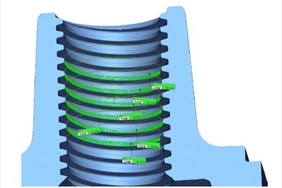
The I.D. measurement for a nut by creating cylindrical features and planes.
Using a blue light 3D scanner, you can capture the nut’s 3D data and then import it into measuring software. There are no shape restrictions, and cross sections can be easily measured after 3D data acquisition. The measurement process is as follows:
- Use 3D scanning to acquire 3D point cloud data.
- Import data into the measurement software and coordinate alignment.
- Measure pitch and profile by making a 2D cross section.
- Measure the nut I.D. and profile flatness by creating cylindrical features and planes.
The measurement accuracy is up to 0.01 millimeter (0.39 inch), and you can scan and measure within one hour.
Using 3D scanning to acquire 3D point cloud data of headlights.
You can also use blue light 3D scanning to perform a full-size inspection of an automobile lamp housing. Deviation caused by processing is a human factor and caused by temperature and humidity that affects accuracy. Plus, the out-of-tolerance dimension also impacts the assembly of lights and related parts. Traditional inspection methods, such as calipers and micrometers, can cause deformation of the workpiece.
A blue light 3D scanner can capture the 3D data of the lamp housing and import that data into the measuring software. The measurement process is as follows:
- Use 3D scanning to acquire the 3D point cloud data of headlights.
- Import the scan and CAD data into the measurement software, align the coordinates and generate the 3D deviation chromatogram.
- Perform full-size measurements.
Measurement accuracy is up to 0.01 millimeter (0.39 inch), and you can complete the whole digitizing and measuring task in three hours.
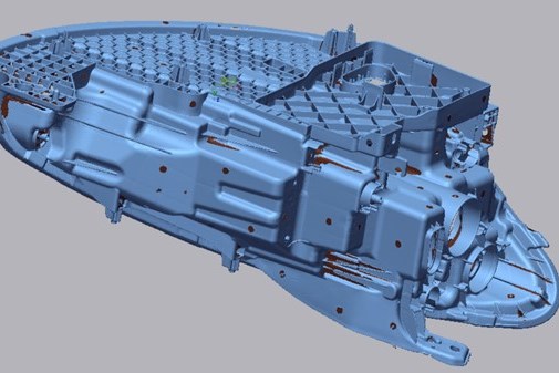
Headlight scan data.
Large-Scale Inspection with Optical Coordinate Measuring
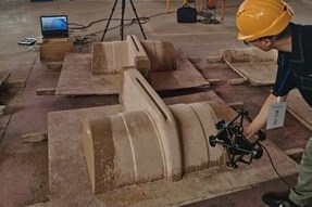
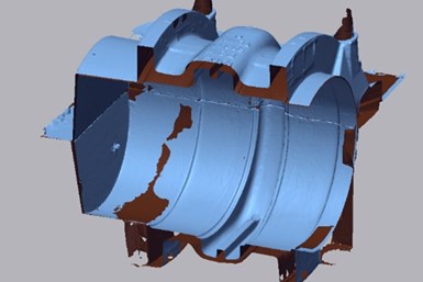
An optical coordinate measuring system collects 3D data of this sand pattern and sand core (top). The assembled core is placed inside the sand pattern to simulate the actual field assembly state (bottom).
Optical coordinate measurement paved the way to fast, efficient and accurate digitization of large objects. For example, using an optical coordinate measuring system to analyze the wall thickness of a sand mold.
Measurement requirements include the thickness inside the cavity of a sand mold. First, use an optical coordinate measuring system to acquire 3D data of the sand pattern and core. The measurement process is as follows:
- Use 3D scanning to acquire 3D point cloud data.
- Separately assemble the sand core and sand pattern using feature alignment in the inspection software.
- Place the assembled core inside the sand pattern to simulate the actual field assembly state.
- Use inspection software to analyze the wall thickness.
Scan time takes 20 minutes, and the measurement time is 20 minutes.
Hybrid Light 3D Scanning Technology
A hybrid light 3D scanner combines the advantages of LED and laser. In rapid scan mode, blue LED structured light captures object data without having to apply reference points. The laser scanning mode is equipped with multiple blue laser lines ensuring accuracy. This also enables the 3D scanning of reflective metal surfaces quickly, which provides high-quality 3D data for reverse design, CAD/CAM and 3D printing.
Reference points are applied on the reflective aluminum mold workpiece before scanning.
The large size of this aluminum mold (1.5 x 1 meters) (4.9 x 3.3 feet) prevents traditional manual measurement tools from obtaining the necessary data accurately, so this mold shop used a dual blue light handheld 3D scanner to measure the mold.
The scanner's portability, user-friendly handling and high scan speed streamlined this complex and improved measurement efficiency. The measuring process used is as follows:
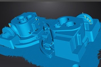
High-precision 3D model data of the aluminum mold.
- Apply reference points. Before scanning, reference points were applied to the reflective aluminum mold workpiece.
- Perform a 3D scan. The laser mode has a scanning speed of 480,000 dots/second. The technician spent only 10 minutes to obtain the complete high-precision 3D model data of the aluminum mold.
- Import the scanned aluminum mold data and a digital model of the original design into measure software to determine accuracy. After the technician aligned the coordinates, he performed a deviation comparison analysis using a chromatogram to obtain the annotated deviation diagram.
- Export measurement report.
The scanning process took fewer than 30 minutes—from applying reference points, 3D scanning to obtaining the final comparison analysis report. The advantages of these inspection and measurement technologies yield efficient time and process management, and high precision.
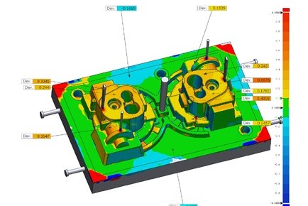
A deviation comparison analysis via a chromatogram yields this annotated deviation diagram.


Related Content

Revisiting Some Hot Runner Fundamentals
What exactly does a hot runner do? If you’ve been in the injection molding industry for any length of time, you might think the answer is obvious, but it is not.
Read More
Plastic Prototypes Using Silicone Rubber Molds
How-to, step-by-step instructions that take you from making the master pattern to making the mold and casting the plastic parts.
Read More
Making Quick and Easy Kaizen Work for Your Shop
Within each person is unlimited creative potential to improve shop operations.
Read More
Machining Center Spindles: What You Need to Know
Why and how to research spindle technology before purchasing a machining center.
Read MoreRead Next

How to Use Continuing Education to Remain Competitive in Moldmaking
Continued training helps moldmakers make tooling decisions and properly use the latest cutting tool to efficiently machine high-quality molds.
Read More
Are You a Moldmaker Considering 3D Printing? Consider the 3D Printing Workshop at NPE2024
Presentations will cover 3D printing for mold tooling, material innovation, product development, bridge production and full-scale, high-volume additive manufacturing.
Read More
How to Use Strategic Planning Tools, Data to Manage the Human Side of Business
Q&A with Marion Wells, MMT EAB member and founder of Human Asset Management.
Read More